Free-space phase shifter having series coupled inductive-variable capacitance devices

a capacitance device and free-space technology, applied in the direction of delay lines, electrical equipment, antennas, etc., can solve problems such as degrading the aerodynamics of aircraft, and achieve the effect of eliminating the loss and weight associated with a conventional corporate feed structur

Inactive Publication Date: 2012-05-15
HRL LAB
View PDF1 Cites 49 Cited by
  • Summary
  • Abstract
  • Description
  • Claims
  • Application Information

AI Technical Summary

Benefits of technology

[0006]The present invention provides a new way of changing the phase of a microwave beam in free space. It allows one to create a steerable antenna using a free space feed, which eliminates the loss and weight associated with a conventional corporate feed structure. A novel aspect of the invention is the free space phase shifting device. This is a lightweight, extended structure that is many wavelengths in size, which accepts a plane wave at one side, and radiates a phase-shifted version of the same plane wave from the other side. In some implementations, it includes a biasing scheme that allows the amount of phase shift to be varied across the area of the device. By programming the phase shifter to produce an arbitrary phase function across its area, one can create nearly any desired radiation pattern, including steering the beam to any desired angle, or producing multiple beams. It can also be used to modulate the wave passing through it, to eliminate the need for a separate phase modulator.
[0007]Large antennas with a free space feed may include steerable reflectarrays or tunable impedance surfaces. Embodiments of the present invention provide advantages over such structures for certain applications because they do not require the geometry necessary for a reflective beam steering apparatus. For example, the phase shifting device can be embedded in the skin of an aircraft, with the source located inside the aircraft and radiating through the phase shifting device to the outside of the aircraft. With a reflective phase shifter, the source would need to be located outside the aircraft, thus degrading the aerodynamics of the aircraft.

Problems solved by technology

With a reflective phase shifter, the source would need to be located outside the aircraft, thus degrading the aerodynamics of the aircraft.

Method used


Image

  • Free-space phase shifter having series coupled inductive-variable capacitance devices
  • Free-space phase shifter having series coupled inductive-variable capacitance devices
  • Free-space phase shifter having series coupled inductive-variable capacitance devices

Examples


Embodiment Construction

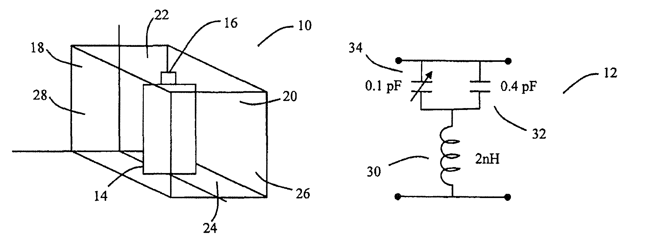
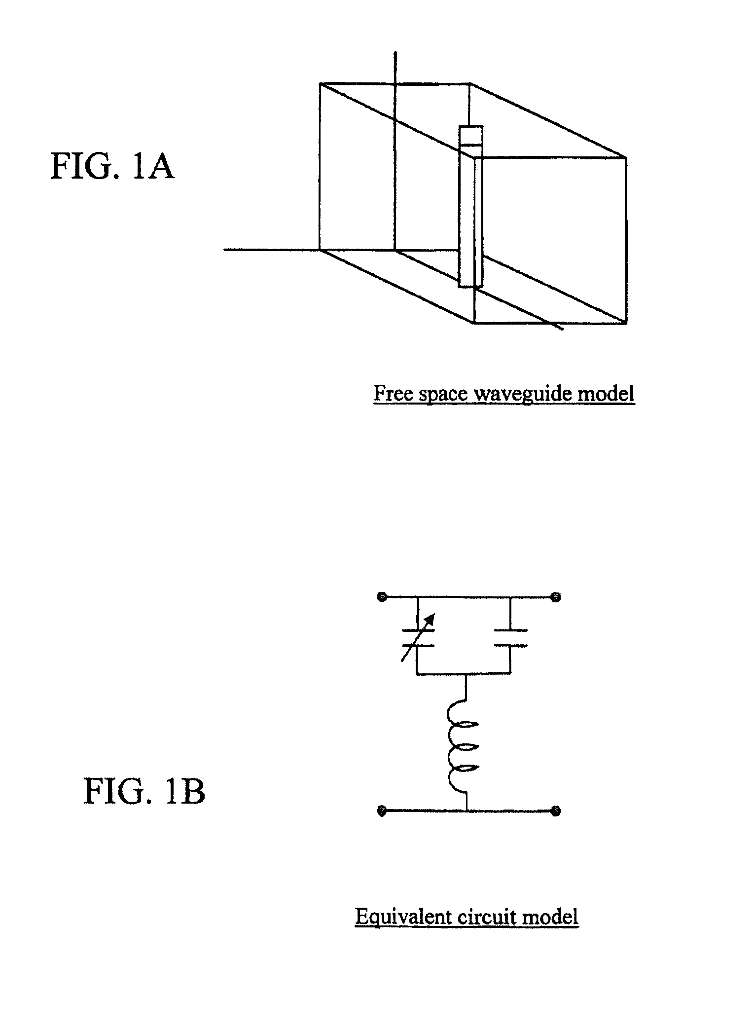
[0037]The free-space phase shifter in accordance with the present invention may be depicted using electromagnetic simulations as shown in FIG. 1A (as developed from a commercial finite element method solver for electromagnetic structures, and, more specifically, developed from the HFSS™ commercial electromagnetic solver software from Ansoft Corporation) and lumped equivalent circuit models as shown in FIG. 1B. In more detail, FIG. 1A shows a free space waveguide model using a commercial electromagnetic solver.

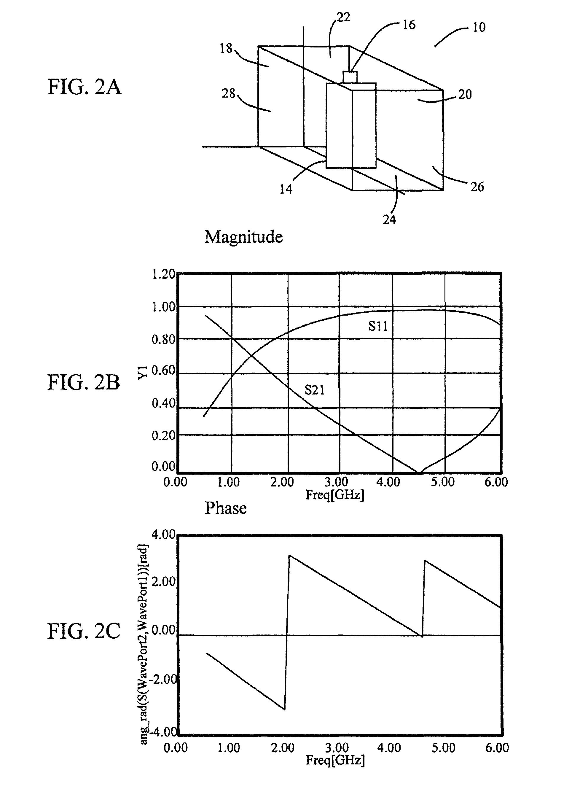
[0038]An electromagnetic simulation is compared with a lumped element circuit model since complicated lumped element circuits can be developed based upon an accurate representation of the electromagnetic simulation. The electromagnetic simulation provides a block section of free space waveguide with electric and magnetic boundary conditions on the boundaries of the block and input and output ports in the direction of wave transmission. Magnitude and phase of transmission (S21) ...


PUM


Abstract

A method of changing phase of a microwave electromagnetic beam in free space is provided wherein a cascade of device layers is located transverse to a path of the microwave beam. Each of the device layers have one or more columns. Each column has a device combination series-coupled to an adjacent device combination in the column. Each device combination has a first device having inductive characteristics at microwave frequencies and a second device series-coupled to the first device. The second device has at microwave frequencies characteristics of a fixed capacitance in parallel with a variable capacitance. The capacitance of one or more of the second devices is variable to establish a desired phase shift and a desired frequency band edge within a desired frequency pass band.

Description

CROSS-REFERENCE TO RELATED APPLICATION(S)[0001]This application is a divisional of U.S. application Ser. No. 11 / 982,477, filed Oct. 31, 2007, now issued as U.S. Pat. No. 7,719,477, issued May 18, 2010, the entire disclosure of which is hereby incorporated by reference herein.BACKGROUND[0002]The present invention relates to phase shifters, and in particular, to phase shifters useable in systems requiring a steerable antenna or an antenna that transmits or receives a modulated signal.[0003]Conventional phase shifters include several classes of devices:[0004]1) Tunable frequency selective surfaces—Tunable frequency selective surfaces provide varying transmission amplitude when the surface is tuned. These structures can also provide a phase shift when they are tuned. However, since this is accompanied by a change in amplitude, they are less useful since it is desirable to have the phase shifter transmit nearly constant amplitude while changing the phase.2) Tunable impedance surfaces—Tun...

Claims


Application Information

Patent Timeline
Patent Type & Authority Patents(United States)
IPC IPC(8): H01Q3/26H01Q3/44H01P1/18
CPCH01P1/182H01P1/185
Inventor SIEVENPIPER, DANIEL FREDERIC
Owner HRL LAB
Why Eureka
Try Eureka