Barn system for housing farm animals

a barn and cage technology, applied in the field of barn systems, can solve the problems of shortening the life of cows, affecting the health of cows, and requiring a lot of labor, and achieve the effect of saving labor

Inactive Publication Date: 2012-05-22
AVILA DAVID
View PDF9 Cites 37 Cited by
  • Summary
  • Abstract
  • Description
  • Claims
  • Application Information

AI Technical Summary

Benefits of technology

[0041]The barn system in accordance with the principles of the present invention also may be constructed and installed in unique and novel ways. The barn components are designed to be assembled at ground level and the pulled and lif

Problems solved by technology

Constant stress on the cows not only means less milk production, but it can also shorten their lives.
The cycle continues until something occurs which makes her an expense rather than an asset.
This something is usually feet, leg, or udder disease problems.
While the temperature and humidity in the barn affect the cow's comfort, another factor that can cause stress in a cow is the absence of light.
Many barns of known designs are dark, and so artificial lighting must be provided, thus raising the cost of power to the owner.
The inherent problem with such tunnel-ventilated barns is that the fresh air traveling through the evaporative pads absorbs water at an uncontrolled rate, which makes the effect of the “wet” air in the barn unpredictable and inconsistent, and thus making control of the humidity in the barn virtually impossible.
Such designs can cause a great deal of stress to the livestock in the barn in the situation where the humidity is at an undesirable level.
However, cross-ventilated barns tend to suffer from a different ventilation problem, na

Method used


Image

  • Barn system for housing farm animals
  • Barn system for housing farm animals
  • Barn system for housing farm animals

Examples


Embodiment Construction

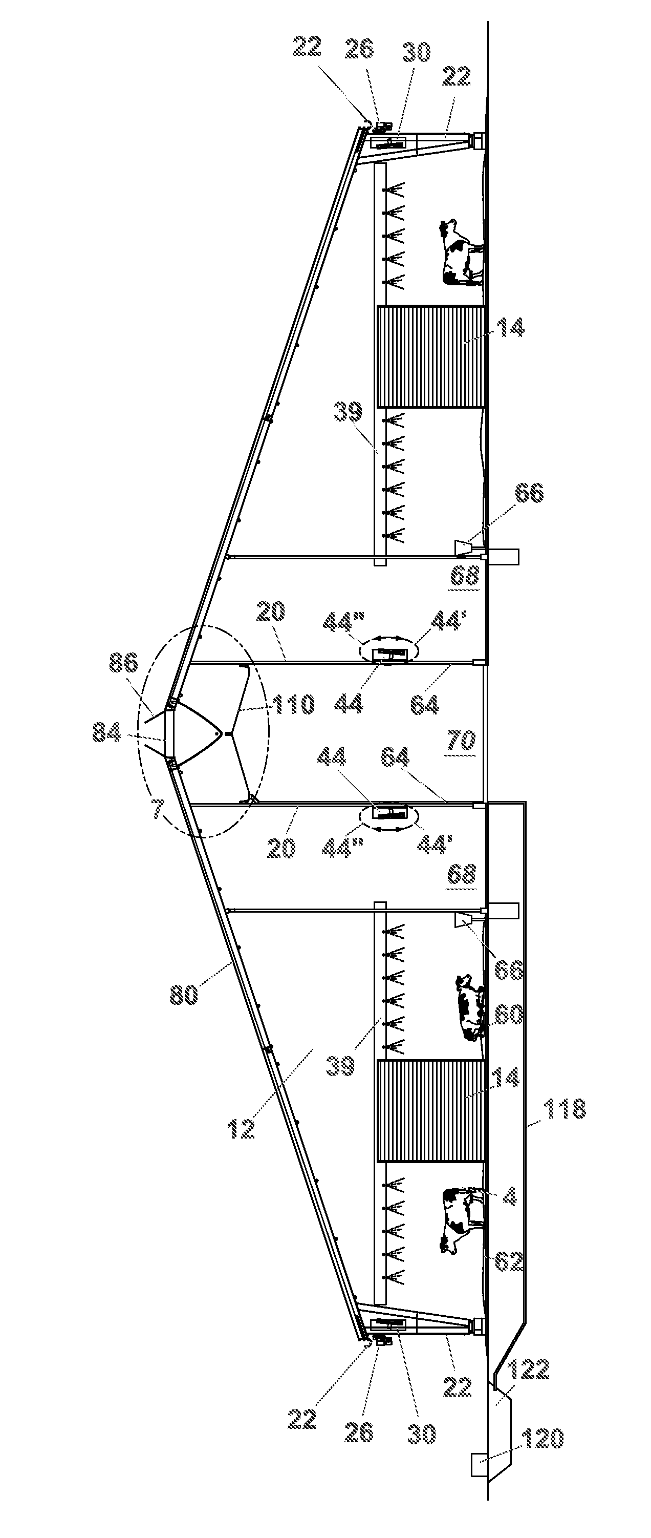
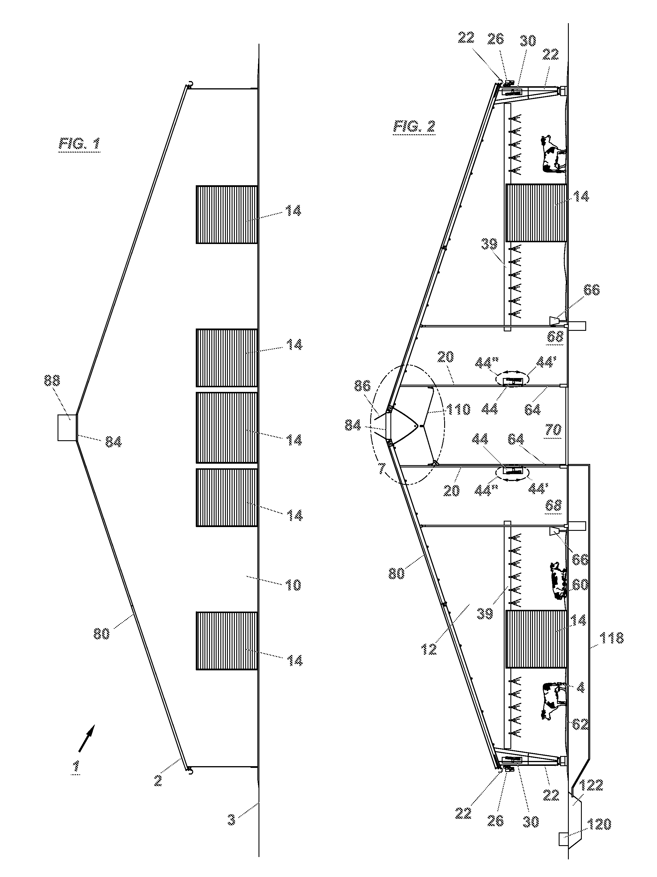
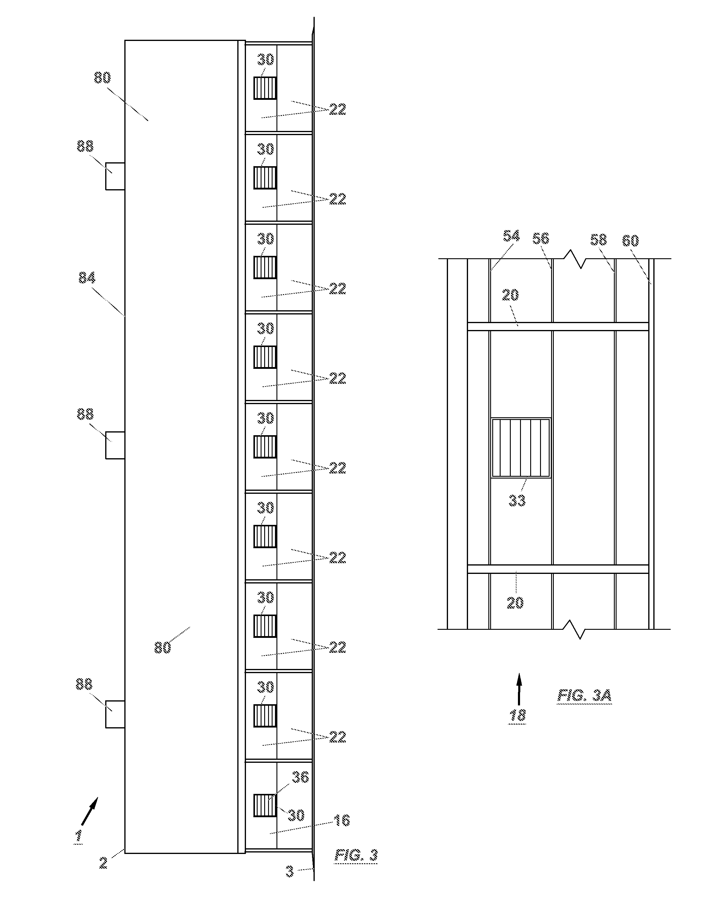
[0057]In the following description of the invention, reference is made to the accompanying drawings, which form a part thereof, and in which is shown, by way of illustration, an exemplary embodiment illustrating the principles of the barn system of the present invention and how it may be practiced. It is to be understood that other embodiments may be utilized to practice the present invention and structural and functional changes may be made thereto without departing from the scope of the present invention.

[0058]A barn system that provides control of the environment inside a closed barn is illustrated in FIGS. 1-5 and is indicated generally by the numeral 1. Barn system 1 includes enclosed barn 2 on grade 3 having front wall 10, rear wall 12 and a pair of opposed side walls 16 extending between front wall 10 and rear wall 12. Roof 80, which has a ridge 84, covers barn 2. A number of cows 4 are housed inside barn 2. Floor 60 of barn 2 is divided into a feed truck lane 70, composting ...


PUM


Abstract

A barn system that enables control of the environment inside a closed barn utilizes banks of fans mounted in the opposing side walls of the barn and interior circulation fans in conjunction with misters to maintain the comfort of animals confined in the barn, in particular, milk cows. The interior circulation fans are of the oscillating type that can sweep in a horizontal arc to help the circulation of the air. Movable curtains in the side walls may be raised and lowered to allow for natural ventilation of the barn when outside conditions allow. A number of exhaust fans mounted on the roof ridge line provides for exhaust of the air out the roof, as opposed to the sides as in conventional barns. The fans, misters, operable ridge vents, exhaust fans and curtains are controlled by a central monitoring and control system. A scrubber system for removing VOC's in the exhaust air may be included. The barn system may also be equipped with a system to remove VOC's from the scrubber water to recycle water back for repeated use in the scrubber system.

Description

RELATED APPLICATIONS[0001]This application claims the benefit of U.S. Provisional Patent Application No. 60 / 931,269 filed May 22, 2007, and U.S. Provisional Patent Application No. 60 / 839,059 filed May 22, 2007, both of which are incorporated herein in their entireties.BACKGROUND OF THE INVENTION[0002]1. Field of the Invention[0003]The present invention relates to the field of farming; more particularly, the present invention relates to a barn system that provides control of the environment inside a closed barn by monitoring conditions both inside and outside of the barn to provide complete animal comfort, in particular to milk cows, with evaporative cooling and improved heat concentration in the winter.[0004]2. General Background and State of the Art[0005]Farm animals, particularly milk cows, confined in a confined environment, are greatly affected by the conditions in the confined environment or barn. If the animals become stressed, the cows will produce less milk. Constant stress ...

Claims


Application Information

Patent Timeline
IPC IPC(8): A01K1/00
CPCA01K1/00A01K1/0047A01K1/0052A01K1/0058A01K1/0082F24F2007/004
Inventor AVILA, DAVID
Owner AVILA DAVID
Why Eureka
Try Eureka