Light absorber device

a technology of light absorption and light, which is applied in the direction of solar heat collectors with working fluids, solar heat collectors for particular environments, etc., can solve the problems of unbalance between the air in the two subspaces, drawback of air obtaining an increased flow resistance, etc., and achieves smoother change of direction, low flow loss, and reduced flow loss

Inactive Publication Date: 2012-05-22
SOLTECH ENERGY SWEDEN
View PDF10 Cites 0 Cited by
  • Summary
  • Abstract
  • Description
  • Claims
  • Application Information

AI Technical Summary

Benefits of technology

[0007]This object is achieved by the light absorbing device of the initially mentioned kind, which is characterised in that the device comprises flow resistance reducing means adapted to reduce the flow resistance for the gaseous medium when it is guided through said path and that said means comprises that the elongated element has an inclination such that said path provides a successively increased width and thus an increased cross section area in the flow direction of the medium in the upper portion of the first subspace and / or in the upper portion of the second subspace. A minimal flow resistance for a medium is obtained in paths having a somewhat expanding cross section area. Such an expansion of the path is also preferable since the gaseous medium expands and is heated. Advantageously, said path has a successively increased cross section area in the flow direction of the medium in at least one portion of the space. Thus, the flow losses can be kept on a substantially minimal level in this whole portion of the space. Advantageously, said element is elongated. Since the element divides the first subspace and the second subspace, the lower end of the elements defines the highest level for the passage between the first subspace and the second subspace. The lower end of the element ought to be located on a level which is located clearly below the levels of the openings in order to provide a stable natural circulation. The level difference between the lower end of the element and the upper edge surface ought to be at least corresponding to the double diameter of the openings. If the inclined element is provided with parallel sides in connection to the first subspace and the second subspace, a corresponding width increase is provided in the flow direction in both the first subspace and the second subspace. By means of such an inclined element, the start of the natural circulation is facilitated as well as the trans-port of the medium through the whole space. By facilitating the natural circulation of the medium, the produced quantity of heat energy can be increased.
[0010]According to another preferred embodiment of the present invention, said flow resistance reducing means comprises at least a guide element which is arranged in at least one portion of the space. Especially, it is required that the medium changes direction in the lower portions of the two subspaces. Inevitably, changes of direction result in flow losses. The application of a suitable guide element in one of these portions results in that the medium can change flow direction in this portion with lower flow losses. The guide element may comprise a plane guiding surface which forms a substantially constant angle to the incident flow direction of the medium. By means of such guide element, the flow losses may be reduced in a simple manner. Alternatively, the guide element may comprise a curved guiding surface which successively changes the flow direction of the incident medium. The medium provides here a smoother change of direction and the flow losses may be reduced further. Several guide elements may be arranged in parallel in said portions in order to further reduce the flow resistance.
[0011]According to another preferred embodiment of the present invention, the second subspace has a larger volume than the first subspace. When the space is subjected to light radiation, the air in the larger second sub area achieves a higher temperature than the air in the smaller first subspace. Thus, a thermal unbalance is created between the airs in subspaces such that a natural circulation in a predetermined direction is achieved. Said flow resistance reducing means may comprise that the second opening has a larger cross section area than the first opening. Thus, the flow of the medium through the space is promoted further. The second opening may have a cross section area which is 1.1 to 2.0 times larger than the first opening. During most circumstances, the optimal flow condition is achieved when the openings are dimensioned within this interval. Advantageously, the lower edges of the first opening and the second opening are located at substantially the same level. Thus, an undesired natural circulation of the medium through the space is prevented to occur when the device is not subjected to solar radiation. The openings do not need to be round but they may have an arbitrary shape. They may, for example, be slit-shaped.
[0012]According to an embodiment of the present invention, said space is delimited by a side of the radiation absorbing material layer which is turned to the transparent material layer. The circulating gaseous medium is here circulated in a space between the outer material layer and the transparent material layer. The device may here be made very thin. According to a second embodiment, said space is delimited by a side of the radiation absorbing material layer which is turned away from the transparent material layer. The circulating gaseous medium is here circulated in a space which is located behind the radiation absorbing material layer. It is here created a second space between the transparent material layer and the radiation absorbing material layer. Advantageously, this second space comprises air or vacuum. Such a second space constitutes an insulation, during operation of the device, between the cool transparent material layer and the warm radiation absorbing material layer. Another advantage with this embodiment, it is that the circulating gaseous medium does not come in contact with the transparent material layer. Such a contact results generally in a fouling of the inner surface of the transparent material layer. Such a fouling reduces the passage of the sunbeams through the transparent material layer and thus also the heat generating capacity of the device. The inner surface of the transparent material layer needs to be cleaned only in exceptional cases.

Problems solved by technology

Thus, a thermal unbalance is obtained between the air in the two subspaces and a natural circulation is established through the light absorber.
However, the use of a labyrinth-shaped path results in the drawback that the air obtains an increased flow resistance.

Method used


Image

  • Light absorber device
  • Light absorber device
  • Light absorber device

Examples


first embodiment

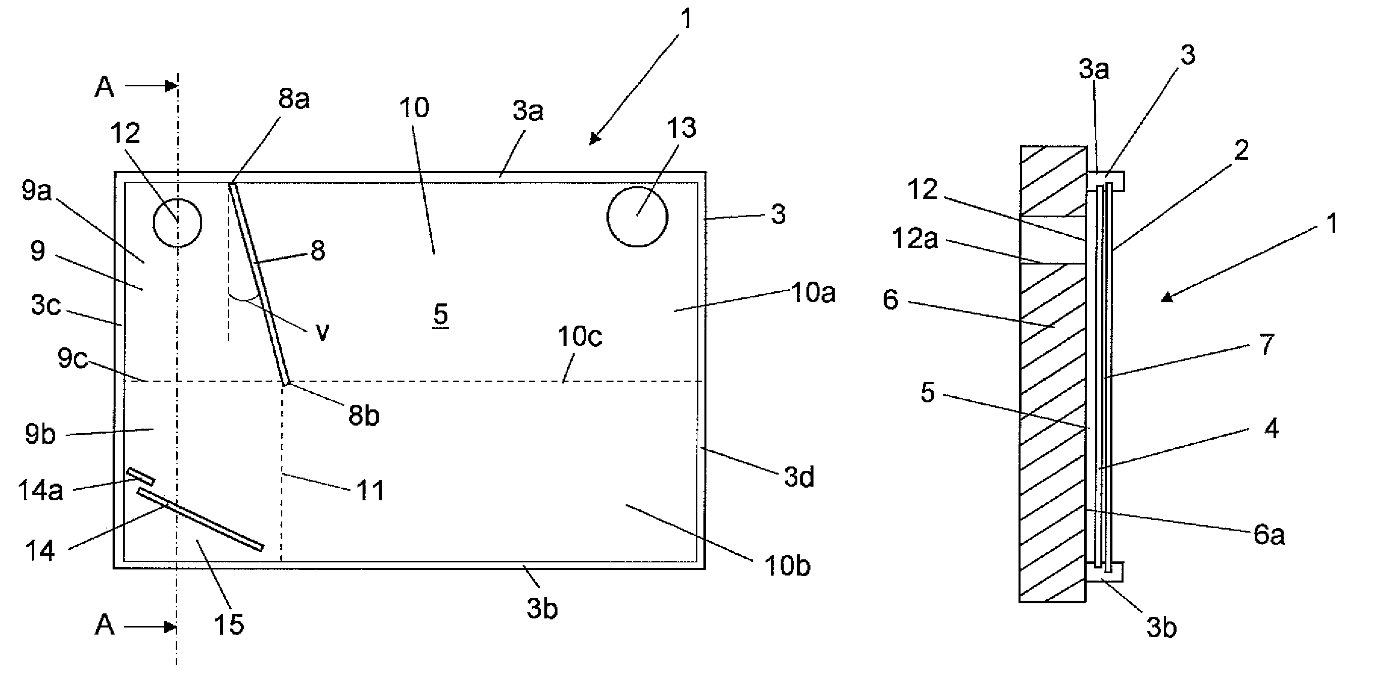
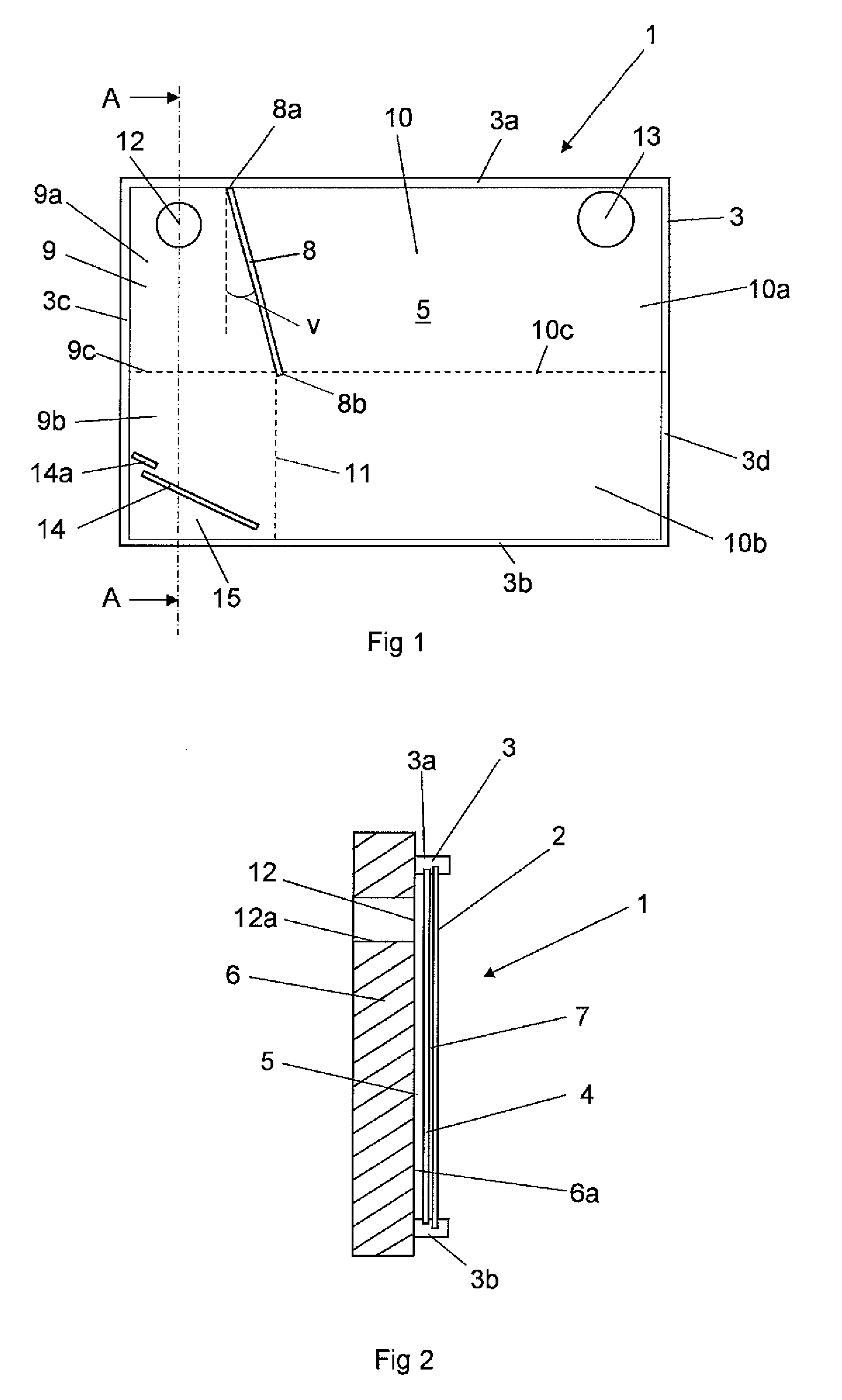
[0018]FIGS. 1 and 2 show a light absorbing device 1 according to the present invention. The light absorbing device 1 comprises an outer material layer of a transparent material which here is exemplified as a plane glass plate 2. However, the outer material layer may be constructed by other materials such as suitable plastic materials. The outer material layer does not need to have a plane outer surface but it may have another shape and be constituted by roofing tiles manufactured by a transparent material. The glass plate 2 is attached in a frame construction 3, which extends around the edges of the glass plates. The frame construction 3 has here a rectangular shape with an upper frame element 3a, a lower frame element 3b and two side frame elements 3c, 3d. Certainly, the frame construction 3 may have another shape.

[0019]The light absorbing device 1 comprises a radiation absorbing material layer which may be a plate 4 provided with a black surface. Certainly, other kinds of radiatio...

second embodiment

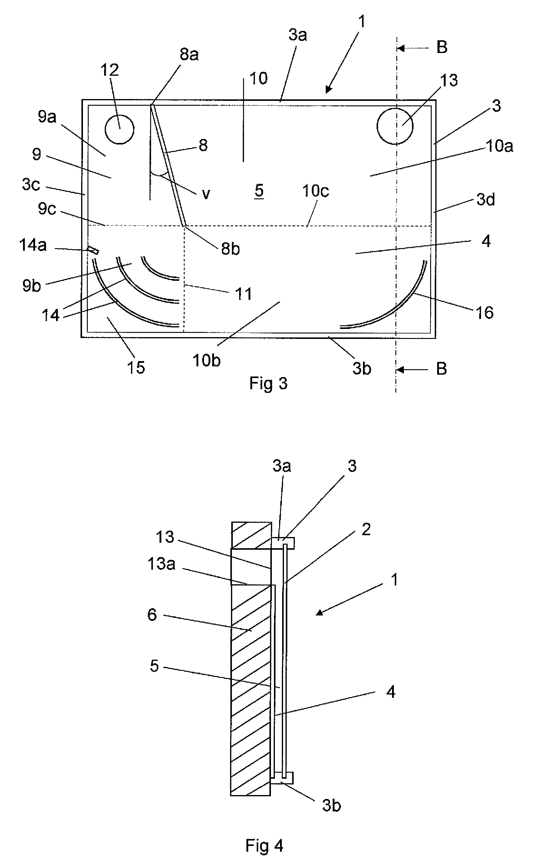
[0026]FIGS. 3 and 4 show a light absorbing device according to a This embodiment differs from the one shown above in that the space 5 for circulation of air here is located in front of the radiation absorbing plate 4. Consequently, the circulating air comes here in contact with the surface of the radiation absorbing plate 4, which is turned to the glass plate 2. The radiation absorbing plate 4 forms here a bottom surface in the space 5. In this embodiment, several guide elements 14 have been applied in den lower part 9b of the first space. The guide elements 14 have here a curved surface for changing the flow direction of the air successively and to guide it through the passage 11 to the second subspace 10. By means of several such curved guide elements 14, the air obtains a further reduced flow resistance. In this case, a lower portion of the second subspace 10 has also been provided with a guide element 16. This guide element 16 has the task to guide the air which flows towards t...


PUM


Abstract

The present invention relates to a light absorbing device which comprises an transparent outer material layer, a space through which air is circulated and heated by light radiation passing through the outer the material layer, a radiation absorbing material layer, and an element which is adapted to divide the space in at least a first subspace, which comprises a first opening, and a second subspace, which comprises a second opening. The air is adapted to flow along a path having an extension from the first opening to the second opening. The path comprises flow resistance reducing means in at least one portion of the space which is adapted to reduce the flow resistance for the gaseous medium when it is guided through said portion of the space.

Description

THE BACKGROUND OF THE INVENTION AND PRIOR ART[0001]The present invention relates to a light absorbing device which comprises an at least partly transparent outer material layer, a space through which a gaseous medium is adapted to be circulated and heated by light radiation passing through the outer material layer, a radiation absorbing material layer which is located in connection to said space, and an element which is adapted to divide the space in at least a first subspace, which comprises a first opening, and a second subspace, which comprises a second opening, wherein the gaseous medium is adapted to flow along a path having an extension from the opening in the first subspace to the opening in the second subspace and that said path has an extension such that the gaseous medium only has possibility to be guided from the first subspace to the second subspace via a passage which is located at a lower level in the space than the levels of the first opening and the second opening, a...

Claims


Application Information

Patent Timeline
Patent Type & Authority Patents(United States)
IPC IPC(8): F24J2/04F24S10/55
CPCF24J2/44F24J2/22Y02E10/44F24J2002/4603F24S10/55F24S90/10F24S2080/05F24S20/66
Inventor MOBERG, ARNEKJAERBOE, PETERBAGE, HENRIKTELANDER, FREDERIC
Owner SOLTECH ENERGY SWEDEN
Why Eureka
Try Eureka