Deflector for a gas turbine strut and vane assembly

a technology of strut and vane, which is applied in the direction of machines/engines, stators, liquid fuel engines, etc., can solve the problem of longer engine configuration

Active Publication Date: 2012-05-22
PRATT & WHITNEY CANADA CORP
View PDF32 Cites 24 Cited by
  • Summary
  • Abstract
  • Description
  • Claims
  • Application Information

AI Technical Summary

Problems solved by technology

The structural struts are typically larger in cross-section than the vanes, and the struts may tend to cause flow separation, particularly when in close proximity to the vanes, which is undesirable.
Conventionally, this problem is addressed by axially spacing the struts apart from the vanes to avoid flow separation, which can result in a longer engine configuration.

Method used


Image

  • Deflector for a gas turbine strut and vane assembly
  • Deflector for a gas turbine strut and vane assembly
  • Deflector for a gas turbine strut and vane assembly

Examples


Embodiment Construction

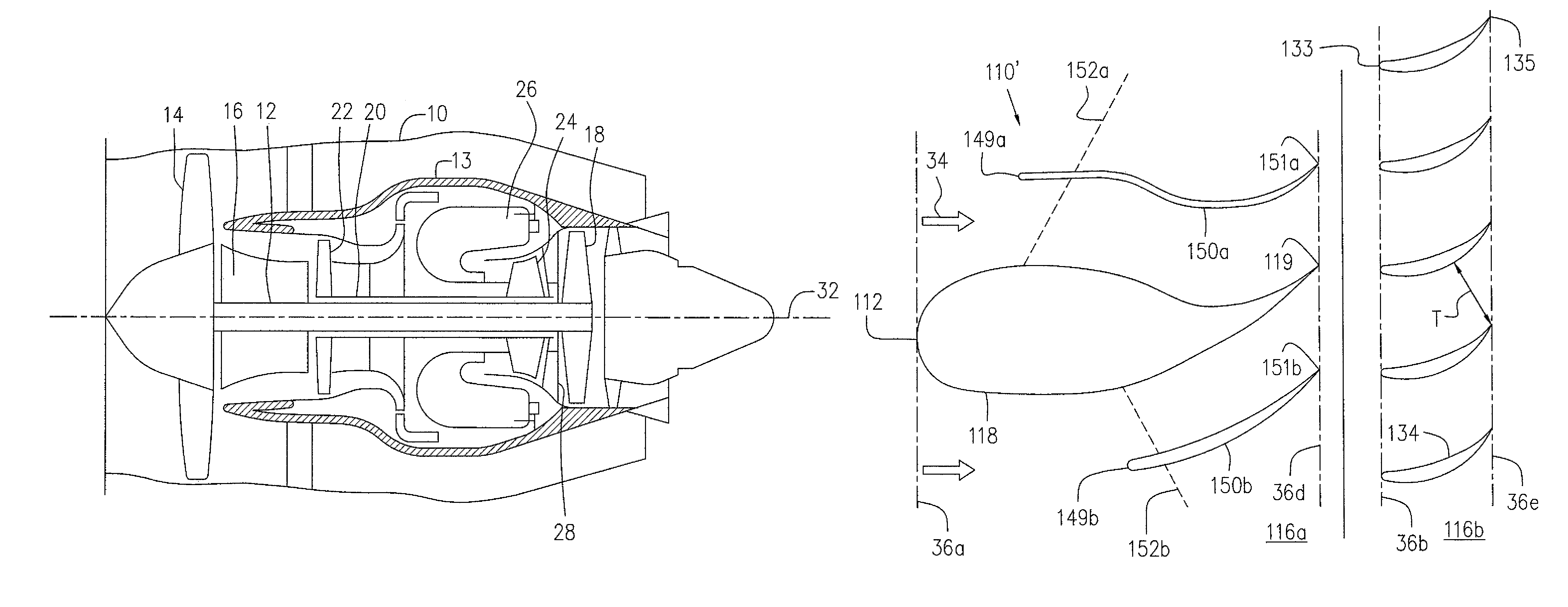
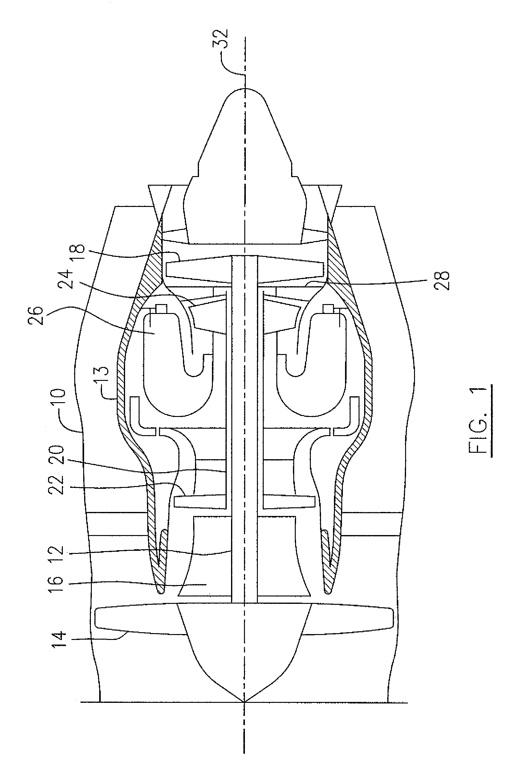
[0014]Referring to FIG. 1, a bypass gas turbine engine has an engine axis 32 and includes a housing or nacelle 10, a casing 13, a low pressure spool assembly which includes a fan assembly 14, a low pressure compressor assembly 16 and a low pressure turbine assembly 18 connected by a shaft 12, and a high pressure spool assembly which includes a high pressure compressor assembly 22 and a high pressure turbine assembly 24 connected by a turbine shaft 20. The core casing 13 surrounds the low and high pressure spool assemblies to define a main fluid path there through. In the main fluid path there is provided a combustor 26 to generate combustion gases to power the high pressure turbine assembly 24 and the low pressure turbine assembly 18. A mid turbine frame system 28 is disposed between the high pressure turbine assembly 24 and the low pressure turbine assembly 18.

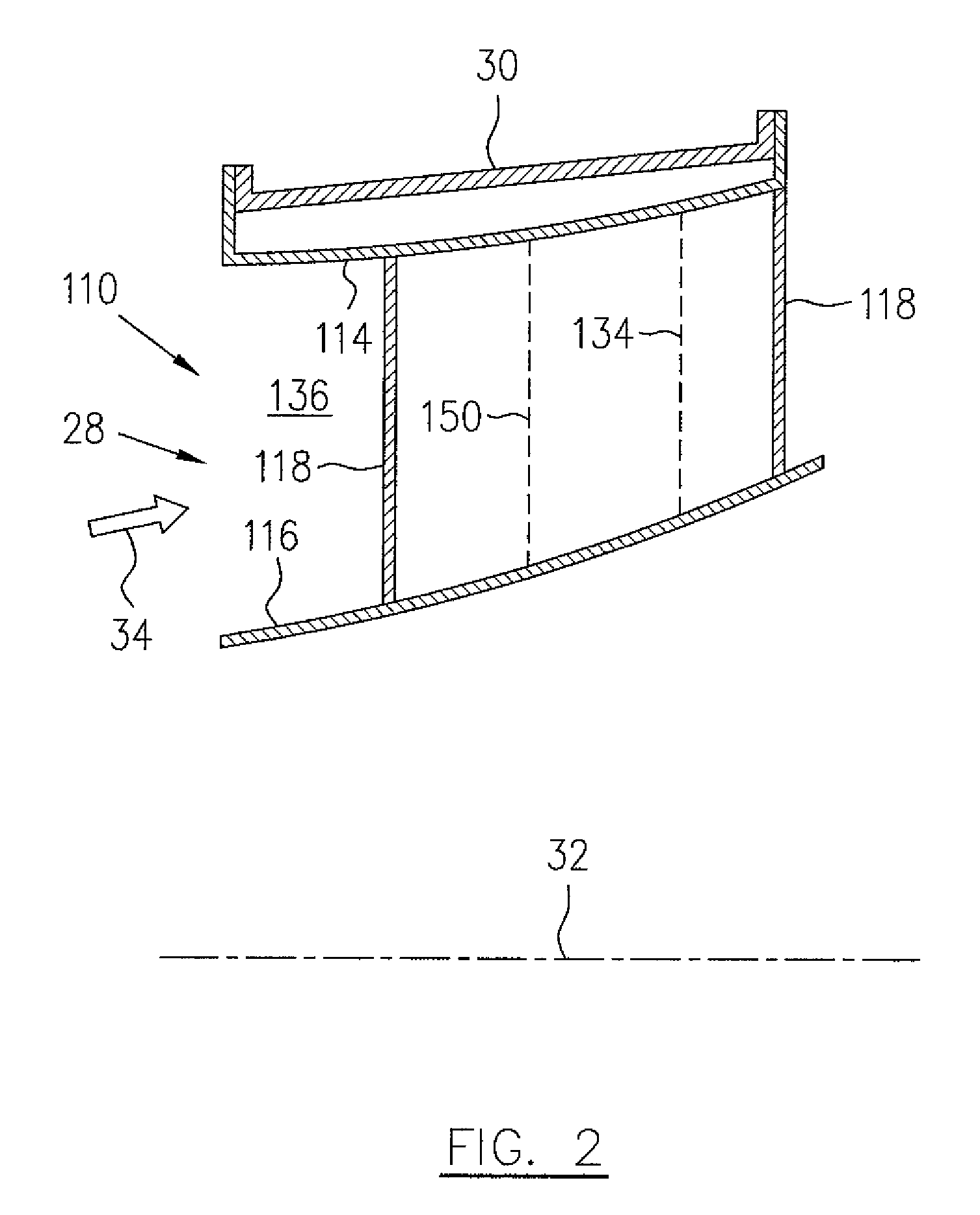
[0015]Referring to FIGS. 1-3, the mid turbine frame (MTF) system 28 includes an annular outer case 30 (see FIG. 2) which ha...


PUM


Abstract

A gas turbine engine is provided having an annular duct having an inner duct wall and an outer duct wall. At least one strut extends between the inner duct wall and the outer duct wall. The strut has an aerodynamic shape. At least one vane located circumferentially adjacent the strut and axially behind a leading edge of the strut, and an aerodynamic deflector located circumferentially between each strut and each vane. The aerodynamic deflector may positioned axially upstream of a flow separation point which would otherwise be caused by the strut.

Description

TECHNICAL FIELD[0001]The application relates generally to gas turbine engines, and more particularly, to a deflector for a strut and vane assembly.BACKGROUND OF THE ART[0002]Gas turbine engine ducts may have structural struts in the gas path flow, as well as stationary airfoil vanes which guide combustion gases through the duct. The structural struts are typically larger in cross-section than the vanes, and the struts may tend to cause flow separation, particularly when in close proximity to the vanes, which is undesirable. Conventionally, this problem is addressed by axially spacing the struts apart from the vanes to avoid flow separation, which can result in a longer engine configuration.[0003]Accordingly, there is a need to provide improvements to the conventional strut and vane architecture.SUMMARY[0004]In one aspect, there is provided a gas turbine engine comprising an annular gas path duct having an inner duct wall and an outer duct wall, the gas path duct having: a plurality ...

Claims


Application Information

Patent Timeline
Patent Type & Authority Patents(United States)
IPC IPC(8): F01D5/14F04D29/38F03D11/00
CPCF01D9/06F01D25/14F01D25/16F01D25/24F01D25/28F04D29/544F01D5/142F01D5/143F01D5/146F01D9/02F01D9/041F01D17/143F02C7/057F02C9/22
Inventor DUROCHER, ERICSLEIMAN, MOHAMADTSIFOURDARIS, PANAGIOTA
Owner PRATT & WHITNEY CANADA CORP
Why Eureka
Try Eureka