Multipoint injector for turbomachine

a multi-point injector and turbomachine technology, applied in the direction of machines/engines, mechanical equipment, lighting and heating apparatus, etc., can solve the problems of fuel stagnation inside the multi-point circuit, inability to achieve cooling, and inability to cook fuel, etc., to achieve easy control

Active Publication Date: 2012-05-29
SN DETUDE & DE CONSTR DE MOTEURS DAVIATION S N E C M A
View PDF5 Cites 13 Cited by
  • Summary
  • Abstract
  • Description
  • Claims
  • Application Information

AI Technical Summary

Benefits of technology

[0016]According to an advantageous embodiment, the first and second ferrules each consist of a one-piece machined part, with at least one part in the form of a first hollow cylindrical ring, the baffles being formed by said first hollow cylindrical ring and a second cylindrical ring housed inside and soldered to the first cylindrical ring and of which the base is perforated by channels opposite the multipoint channels, in order to control the cooling / supply rate, in the pilot injection channels. Until now, the baffles were made by machining, essentially by electroerosion, directly and partially in one of the two one-piece ferrules. More specifically, this direct machining in a one-piece part does not allow grooves of low height to be formed, i.e. baffles of low height. The sections of the baffles and thus of the circuits machined directly in one piece may thus be adapted according to the desired flow and velocity. Machining two hollow cylindrical rings of different section, then housing one thereof in the other and finally soldering them together makes it possible to obtain sections of very precise dimensions. Thus, it is possible to adapt said sections easily to the desired fuel flow and / or velocity. Moreover, conventional techniques of machining may be used without resorting to machining by electroerosion.
[0017]In other words, separating the external ring into two separate parts makes it possible to control the geometry of the baffles and thus the rate of cooling / supply of the pilot injection.
[0018]According to an advantageous embodiment, the admission chamber is formed in the first ferrule and communicates with the injection nozzle by means of a pipe not passing through the swirlers or any space separating them. Thus according to this embodiment, the pilot circuit is connected to the injection nozzle by means of the exterior of the injection head. This makes it possible to dispense with the perforation of additional channels in the swirlers as currently implemented. This also makes it possible to obtain further configurations of the multipoint injector with fine swirlers and / or swirlers of the multi-swirler type, i.e. with a plurality of swirler stages. More specifically, in these configurations of the injector, it is not possible to perforate the swirlers or to pass through a plurality of stages.
[0020]Further preferably, the pipe is a tube bent in a U-shape, of which one of the branches connected to the hub of the stage of swirlers extends along the axis of the injection nozzle and the other of the branches connected in parallel to the admission chamber extending in parallel to the axis of the injection nozzle. Thus a connection is obtained which has a small spatial requirement and which does not prevent or hardly prevents the entry of air onto the swirlers. The use of a bent and soldered tube is furthermore easy to implement and cost-effective.
[0035]Such a method which uses soldering of two one-piece parts to one another and the previous machining thereof makes it possible, therefore, to create sections of the cooling circuit of the multipoint fuel which are of dimensions which may be easily controlled.

Problems solved by technology

At raised temperatures, the intermittent operation of the multipoint circuit has the major drawback of causing decomposition, otherwise known as coking, of the fuel stagnating inside the multipoint circuit when the flow thereof is considerably reduced, or even cut off.
Unfortunately, until now, the structure of the existing multipoint injectors has been such that the two pilot and multipoint circuits overlap one another.
More specifically, such overlapping does not allow the cooling to be achieved in a satisfactorily uniform manner.

Method used


Image

  • Multipoint injector for turbomachine
  • Multipoint injector for turbomachine
  • Multipoint injector for turbomachine

Examples


Embodiment Construction

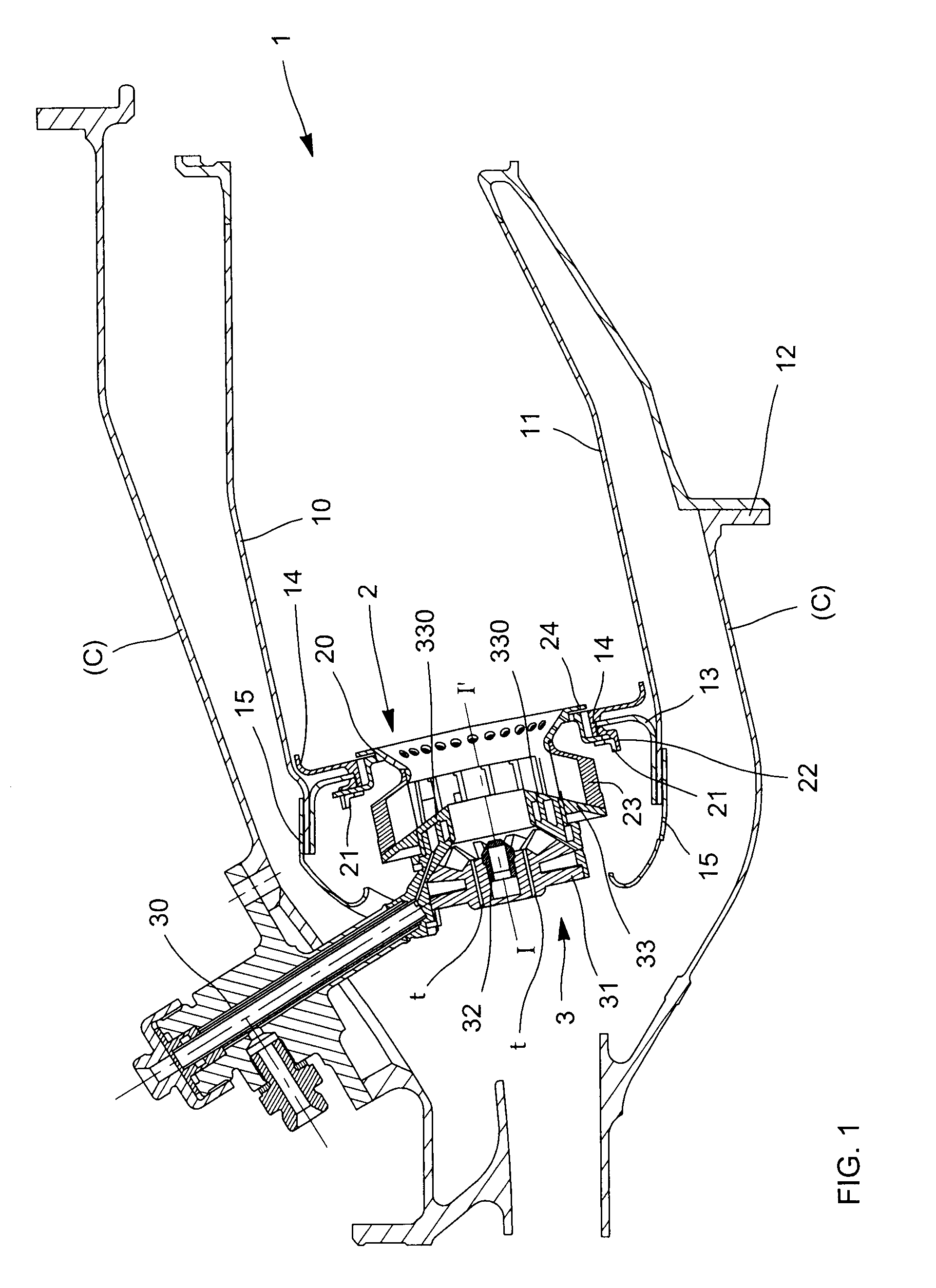
[0051]A part of the combustion chamber 1 of a turbomachine is shown in FIG. 1. The combustion chamber 1 usually comprises an external wall 10, an internal wall 11, flanges for fastening the internal 10 and external 11 walls (not shown) to the chamber housing C in a junction zone 12, a chamber base 13 bolted or welded to the walls 10, 11, a deflector 14 to protect the chamber base 13 from the radiation of flames as a result of the combustion, various one-piece or separate fairings 15 and finally a plurality of injection systems 2 in each of which is mounted an injector 3. In FIG. 1 only one injection system 2 with one injector 3 is shown: a revolving combustion chamber usually comprises a large number of injectors 3, generally from 10 to 50, the number depending on the power of the engine to be supplied. Each injection system 2 comprises a bowl 20 diverging toward the inside of the chamber to cause the emerging jet of the air and fuel mixture to ignite, a floating ring 21 for sliding...


PUM

PropertyMeasurementUnit
diametersaaaaaaaaaa
diameteraaaaaaaaaa
diametersaaaaaaaaaa

Abstract

A multipoint injector for a turbomachine according to which any risk of fuel coking is eliminated is disclosed. The multipoint fuel which is liable to stagnate inside the circuit thereof is cooled uniformly, due to the formation of continuous baffles which each communicate with at least one separate circulation channel and of which the peripheral baffles open out into a fuel admission chamber arranged in a zone diametrically opposing the circulation channels and which communicates with the injection nozzle for pilot fuel in order to achieve uniform supply and cooling of the injector.

Description

BACKGROUND OF THE INVENTION AND DESCRIPTION OF THE PRIOR ART[0001]The invention relates to a multipoint injector intended to be mounted in an injection system fixed to a combustion chamber housing of a turbomachine, such as an aircraft engine.[0002]It relates more particularly to the structure of such an injector and, in particular, the part of the structure dedicated to supplying the pilot circuit and multipoint circuit and to the cooling thereof.[0003]Fuel injectors known as “multipoint” fuel injectors are a new generation of injectors which make it possible to adapt to different speeds of the turbomachine. Each injector is provided with two fuel circuits: that known as the “pilot” circuit which has a continuous flow optimized for low speeds and that known as the “multipoint” circuit which has an intermittent flow optimized for high speeds. The multipoint circuit is used when it is necessary to have additional thrust from the engine, in particular in the cruising and take-off phas...

Claims


Application Information

Patent Timeline
Patent Type & Authority Patents(United States)
IPC IPC(8): F02C1/00
CPCF23D11/36F23R3/343F23R3/283F23D2900/00016Y10T29/49446Y10T29/49412Y10T29/49419
Inventor HERNANDEZ, DIDIER HIPPOLYTENOEL, THOMAS OLIVIER MARIE
Owner SN DETUDE & DE CONSTR DE MOTEURS DAVIATION S N E C M A
Why Eureka
Try Eureka