
System and method for airflow sensing and monitoring

a technology of airflow sensing and monitoring system, applied in the field of heating, ventilating and air conditioning systems, can solve the problems of reducing system efficiency, increasing energy costs, excessive maintenance and repair costs, etc., and achieve the effect of ensuring maximum energy efficiency and filtration effectiveness

Active Publication Date: 2012-05-29
KELLEY ROY
View PDF1 Cites 10 Cited by
  • Summary
  • Abstract
  • Description
  • Claims
  • Application Information

AI Technical Summary

Benefits of technology

[0011]Accordingly, it is an object of the present invention to eliminate the hurdles of known methods for measuring and monitoring HVAC airflow conditions and allow an HVAC technician of average skill to accurately and precisely determine the airflow conditions and correct airflow deficiencies for any HVAC system. It is a further objective of the present invention to provide the ability to monitor an HVAC system during its useful life to assure maximum energy efficiency and filtration effectiveness.

Problems solved by technology

Low airflow reduces system efficiency (SEER), increases energy costs, results excessive maintenance and repair costs, and leads to premature failure of equipment.
Current methodology to measure and establish proper airflow is problematic and unreliable.
Methods known in the art, such as placing an air velocity meter inside an AC duct and then estimating the cross-sectional area of the duct, are far too complex and prone to inaccuracy for field technician charged with effectively diagnosing problems with AC systems.
More accurate and precise methods of measuring and establishing proper airflow typically require extensive technician training, and expensive instrumentation and installation costs.
The clear downside to these flow hoods is that the large housing often renders the flow hood useless in buildings where the grills are too close to other structural elements and therefore the flow hood, while accurate, simply cannot be used.
However, this indirect method of calculating airflow velocity can be very imprecise and inaccurate due to the stratification of the temperature gradient across the system and therefore is not effective in diagnosing problems within the HVAC system, whether up-stream or down-stream from the air handling unit.
Known means for monitoring the performance and efficiency of an HVAC system have severe limitations.
Typical thermostats known in the art do not monitor the actual airflow conditions in its attendant HVAC system.
While some of these thermostats have the ability to inform the user whether a filter change is needed, this indication is usually based solely on the length of operation of the HVAC system between filter changes and does not take into account the actual airflow conditions within the system.

Method used


Image

  • System and method for airflow sensing and monitoring
  • System and method for airflow sensing and monitoring
  • System and method for airflow sensing and monitoring

Examples


Embodiment Construction

[0019]While the present invention will be described more fully hereinafter with reference to the accompanying drawings, in which one or more embodiments of the present invention are shown, it is to be understood at the outset of the description which follows that persons of skill in the appropriate arts may modify the invention herein described while still achieving the favorable results of this invention. Accordingly, the description which follows is to be understood as being a broad, teaching disclosure directed to persons of skill in the appropriate arts, and not as limiting upon the present invention.

[0020]Pressure Plate

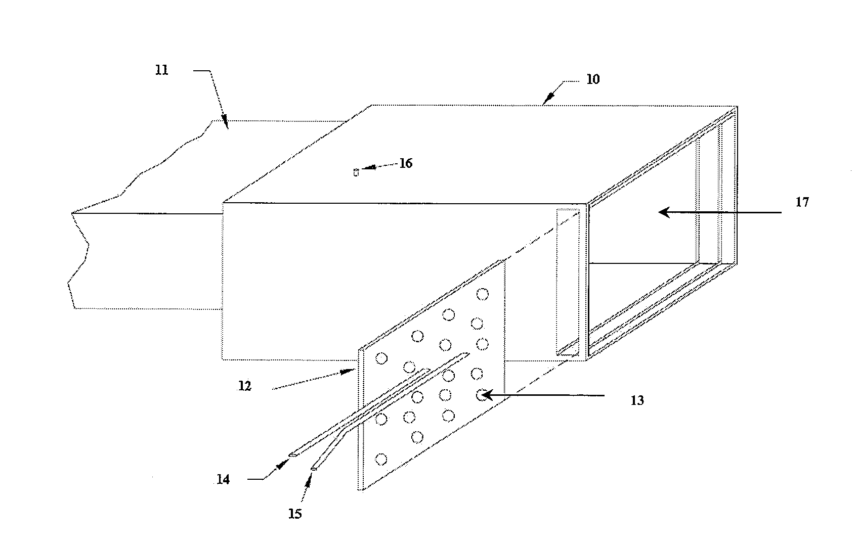
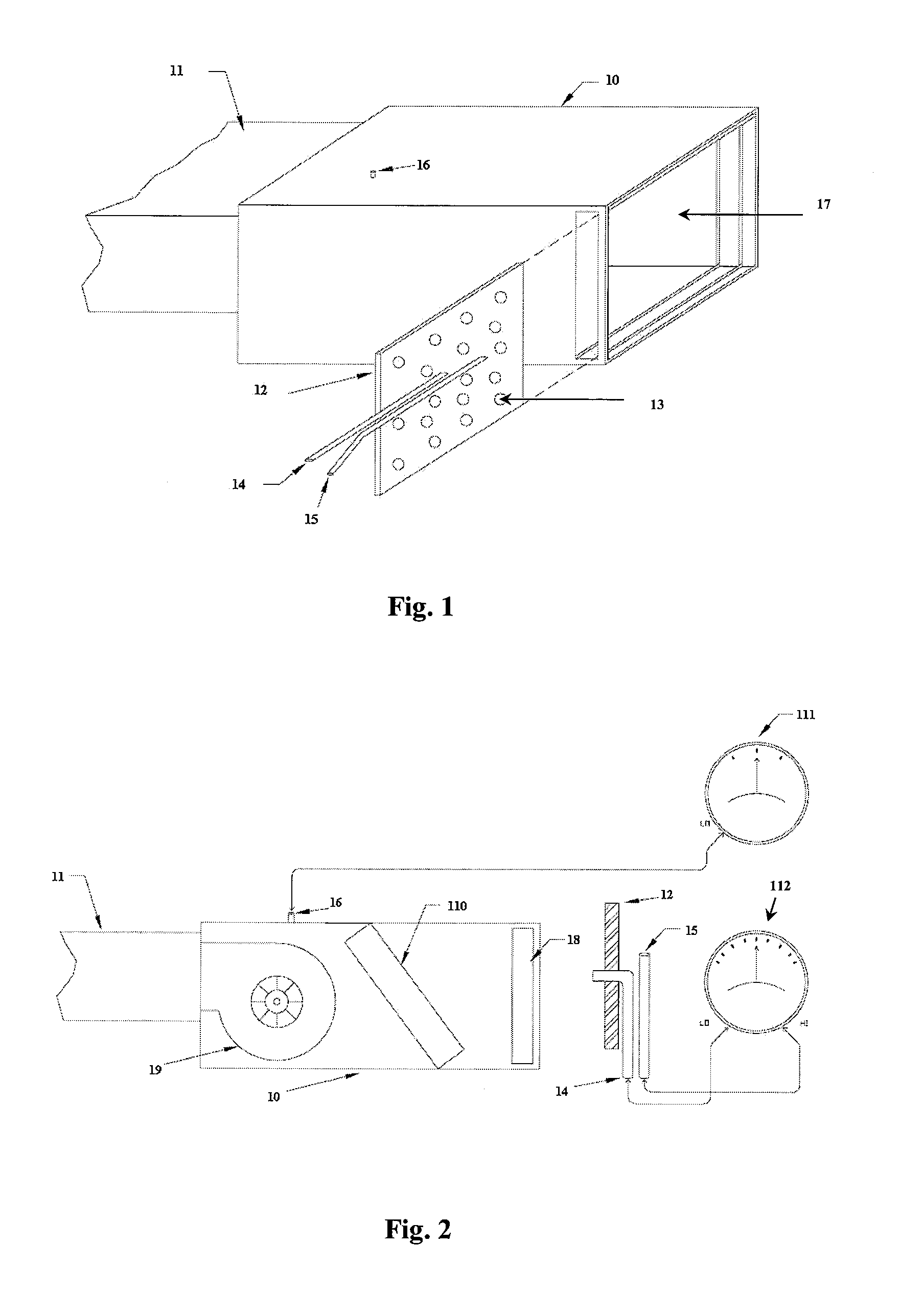
[0021]FIG. 1 depicts one embodiment of the system of the present invention. Shown is air handling unit 10, supply duct 11, perforated pressure plate 12 containing a plurality of apertures 13, and flexible leads 14 and 15. Air flows into the system in the direction of arrow 17. With reference to FIG. 2, also shown is filter rack 18, blower 19, and heating element ...


PUM


Abstract

A system and method for measuring the airflow in an air handling unit, comprising a pressure plate with a plurality of apertures having a known surface area, a differential pressure manometer, and two. The first end of the leads is attached to a differential pressure manometer and second end of the leads is attached to the pressure plate. The pressure plate is placed in the filter rack of an air conditioning system the differential pressure manometer measures the differential pressure loss across the pressure plate allowing the user to determine airflow conditions and the location of obstructions. Additional embodiments of the system and method herein include placing two sensor tubes having apertures along the thereof at specific locations within the air handling unit that, when attached to a manometer, measure the differential pressure loss across the two locations. Various methods for establishing and monitoring proper airflow in an air handling unit are also contemplated.

Description

PRIORITY INFORMATION[0001]This application claims the benefit of U.S. Provisional Application No. 61 / 230,916, filed Aug. 3, 2009, and U.S. Provisional Application No. 61 / 354,807, filed Jun. 15, 2010.TECHNICAL FIELD[0002]The present invention relates generally to heating, ventilating and air condition (“HVAC”) systems and more specifically to systems and methods for sensing, measuring, and monitoring airflow conditions within HVAC systems.BACKGROUND OF THE INVENTION[0003]Proper airflow is a critical component to assure maximum efficiency in forced-air ducted air conditioning (AC) systems. The Department of Energy sponsored Energy Star Survey determined that more than 50% of air-conditioning installations have low airflow. Low airflow reduces system efficiency (SEER), increases energy costs, results excessive maintenance and repair costs, and leads to premature failure of equipment.[0004]Current methodology to measure and establish proper airflow is problematic and unreliable. Methods...

Claims


Application Information

Patent Timeline
Patent Type & Authority Patents(United States)
IPC IPC(8): G01F1/34
CPCG01F1/42
Inventor KELLEY, ROY
Owner KELLEY ROY
Learn More