Shifting device for an automatic transmission

a technology of shifting device and automatic transmission, which is applied in the direction of mechanical control device, process and machine control, instruments, etc., can solve the problems of reducing the service life of the shifting device, and affecting the play of children, etc., and achieves the effect of high load, high load, and extremely fast shifting

Inactive Publication Date: 2012-05-29
DR ING H C F PORSCHE AG
View PDF25 Cites 8 Cited by
  • Summary
  • Abstract
  • Description
  • Claims
  • Application Information

AI Technical Summary

Benefits of technology

[0011]The present invention deals with the problem of providing, for a shifting device of the type indicated above, an improved or at least a different embodiment, which is characterized in particular in that it realizes improved shifting convenience or actuation convenience and / or that it has increased stability and / or that it comprises a higher level of failure safety.
[0012]The invention relates to the general idea of realizing a drive connection between the release button and two blocking elements, where the blocking elements are arranged on the gear-shift lever with freedom to move up and down, and where the blocking elements are also arranged in redundant fashion. The two blocking elements are arranged in such a way that an actuation of the release button produces a synchronous stroke of the two blocking elements. Each of the blocking elements cooperates with an arresting gate, which comprises gate sections assigned to the gear-shift positions. In the gear-shift position in question, each blocking element cooperates with its associated gate section to prevent the gear-shift lever from moving out of the locked state. The stroke of the blocking element which occurs when the release button is actuated has the effect of disengaging the blocking element from the gate section in question and allows the gear-shift lever to be moved into a new position. As a result of this actuation of the release button, the locking mechanism is converted to a released state. The redundant design of the blocking element based on the provision of two synchronously operating or synchronously acting blocking elements reduces the mechanical load on the individual blocking element; in particular, it cuts that load in half, which prolongs the service life of the shifting device. If one of the blocking elements fails, furthermore, a fallback position exists, because the other blocking element remains functional. Overall, the shifting device thus offers a higher degree of failure safety.
[0013]In an alternative solution of this problem, the invention relates to the idea of equipping a blocking mechanism for blocking the gear-shift lever in the Park position with two redundantly arranged blocking elements, each of which cooperates with a blocking gate. The blocking gate comprises a gate section assigned to the Park position. The two blocking elements and the minimum of one blocking gate are coordinated with each other in such a way that, when the Park position is present, each blocking element is aligned with the assigned gate section and can engage therein, thus producing the blocking effect. The blocking mechanism is provided in addition to the locking mechanism and can, under certain conditions, block the gear-shift lever in the Park position, so that it cannot be moved out of the Park position even when the release button is used to convert the locking mechanism into its released state. For example, the blocking mechanism can be connected to an ignition lock of the vehicle, so that the blocking action is released only when the ignition key is inserted. It can also be provided that, in addition, a brake pedal of the vehicle must be actuated to release the blocking action. An embodiment of this type, which is also called a “shift lock”, reduces the risk of incorrect operation of the shifting device. It forms in particular a child safety device, which makes it more difficult for children playing in the vehicle to cause the vehicle to roll away unintentionally. According to aspects of the invention, two redundantly arranged blocking elements are provided, as a result of which the load on the individual blocking element is reduced and the service life of the shifting device is prolonged. In addition, the redundant arrangement of the blocking elements increases the failure safety of the shifting device, because the function of the blocking mechanism can remain guaranteed even if one of the blocking elements should fail.
[0014]According to an advantageous embodiment, two arresting gates can be provided, where each of the two blocking elements cooperates with one of these arresting gates. As a result, the load on the individual arresting gate is reduced, which increases the service life and the failure safety of the shifting device.
[0016]The shifting device presented here is especially suitable for use in conjunction with a dual-clutch automatic transmission. A dual-clutch automatic transmission of this type makes it possible to shift extremely quickly from one gear to the next. The proposed shifting device offers the possibility of exploiting this property of the dual-clutch transmission in an especially effective manner. In particular, dynamic shifting operations can be realized in the automatic shift track when maneuvering or when the automatic transmission is actuated in the manual shift track. Dynamic shifting operations or dynamic actuating operations which are possible with such a dual-clutch transmission require an especially sturdy shifting device, which can be subjected to high loads. The proposed shifting device has the desired high degree of sturdiness and operating reliability. The dual-clutch automatic transmission can be designed in an especially advantageous manner as a seven-gear automatic transmission, which comprises seven forward gears. In addition, the shifting device presented here is especially suitable for use in sports vehicles or in a vehicles with a rear-mounted engine. Dynamic shifting operations are frequently desired precisely in the case of sports vehicles, especially those with a rear-mounted engine. As a result of higher degree of actuation convenience and its increased reliability, the sturdy shifting device presented here makes such dynamic shifting operations possible.

Problems solved by technology

The redundant design of the blocking element based on the provision of two synchronously operating or synchronously acting blocking elements reduces the mechanical load on the individual blocking element; in particular, it cuts that load in half, which prolongs the service life of the shifting device.
It forms in particular a child safety device, which makes it more difficult for children playing in the vehicle to cause the vehicle to roll away unintentionally.

Method used


Image

  • Shifting device for an automatic transmission
  • Shifting device for an automatic transmission
  • Shifting device for an automatic transmission

Examples


Embodiment Construction

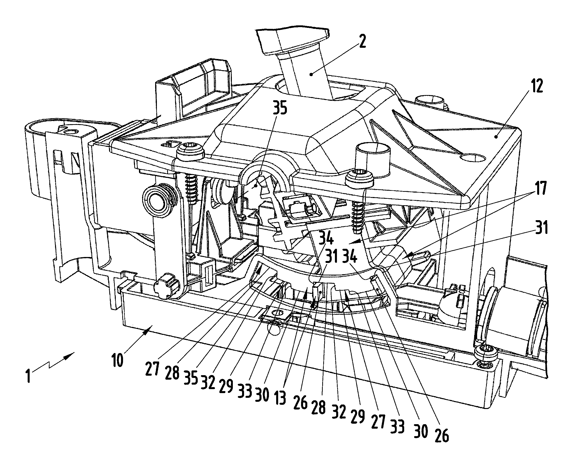
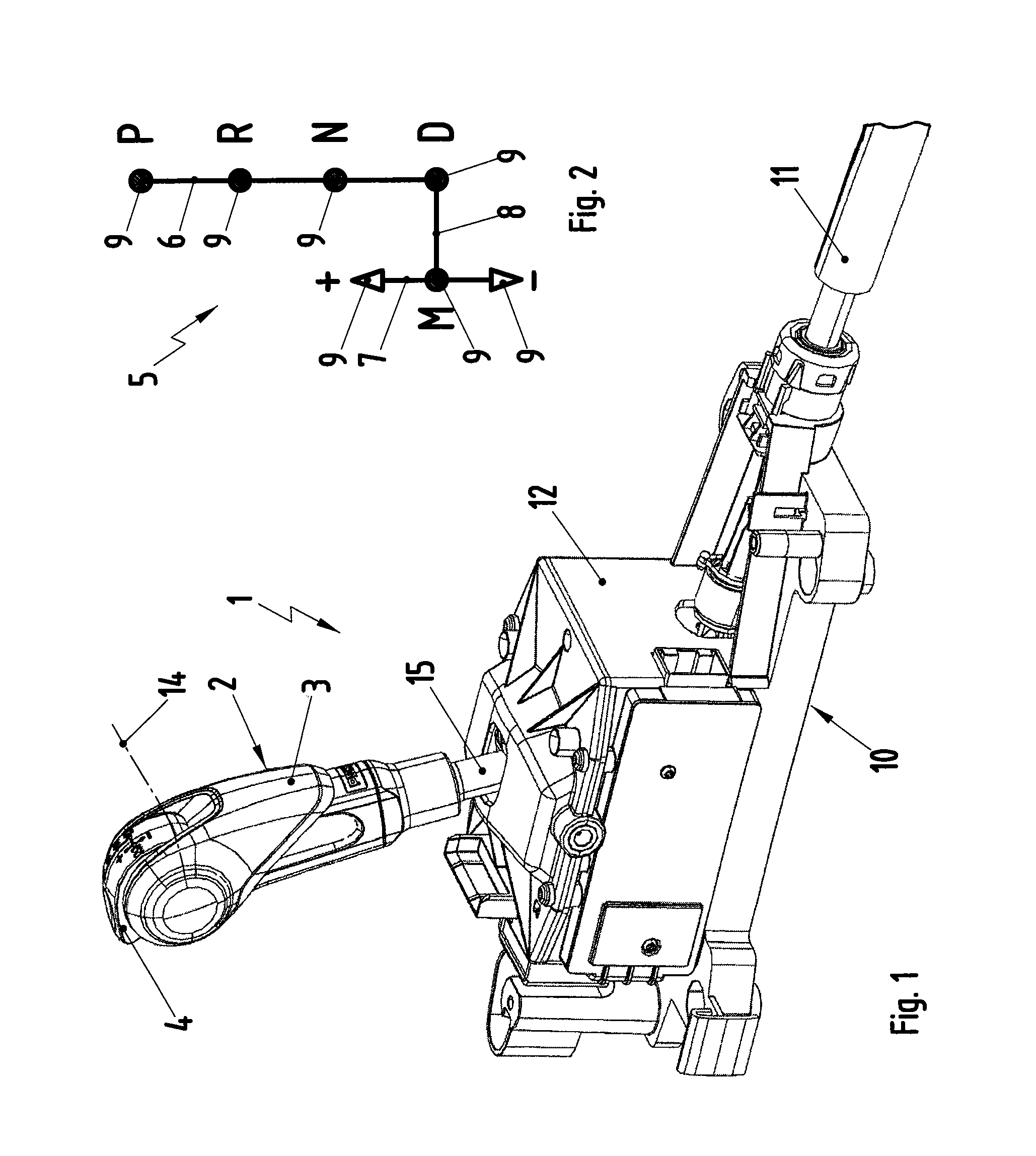
[0024]As shown in FIG. 1, an inventive shifting device 1, which is used in conjunction with an automatic transmission of a motor vehicle, comprises a gear-shift lever 2, which comprises a hand grip 3. A release button 4, which, in this example, is integrated into the hand grip 3, is also provided on the gear-shift lever 2. The gear-shift lever 2 can be moved in a shift gate 5, a simplified view of which is shown in FIG. 2. The shift gate 5 comprises an automatic shift track 6, a manual shift track 7, and a transverse track 8 The gear-shift lever 2 can be moved in the automatic shift track 6 and in the manual shift track 7 to select gear-shift positions 9. For example, the automatic shift track 6 comprises the following gear-gear-shift positions: Park P, Reverse R, Neutral N, and Drive D. In contrast, the manual shift track 7 comprises, for example, a Middle M position, an upshift position +, and a downshift position −. The transverse shift track 8 allows the gear-shift lever 2 to be...


PUM


Abstract

A shifting device for an automatic transmission of a motor vehicle with a gear-shift lever, which can be moved in an automatic shift track to select gear-shift positions; with a locking mechanism for blocking the adjusting movements of the gear-shift lever into at least one gear-shift position and / or out of at least one gear-shift position; and with a release button arranged on the gear-shift lever to release the blocking action of the locking mechanism. An increased level of functional reliability can be achieved by establishing a drive connection between the release button and two blocking elements, which are arranged redundantly on the gear-shift lever with the freedom to move up and down, that an actuation of the release button produces a synchronous stroke of the two blocking elements, where each of the blocking elements cooperates with an arresting gate comprising gate sections assigned to the gear-shift positions.

Description

CROSS REFERENCE TO RELATED APPLICATIONS[0001]This U.S. patent application claims priority to German Application DE 10 2008 022 550.9, filed Apr. 30, 2008, which is incorporated by reference herein in its entirety.FIELD OF THE INVENTION[0002]The present invention pertains to a shifting device for an automatic transmission of a motor vehicle.BACKGROUND OF THE INVENTION[0003]A shifting device for an automatic transmission of a motor vehicle which comprises a gear-shift lever, which can be moved in an automatic shift track to select gear-shift positions, is known from DE 100 57 299 A1. This automatic shift track can comprise, for example, gear-shift positions for Park, Reverse, Neutral, and Drive. The known shifting device also comprises a locking mechanism, which can be switched at least between a locked state and a released state. It also comprises a release button for changing the state of the locking mechanism. In the locked state, the locking mechanism blocks the movement of the ge...

Claims


Application Information

Patent Timeline
Patent Type & Authority Patents(United States)
IPC IPC(8): B60K20/00G05G5/08
CPCF16H59/10F16H61/22B60K20/00F16H59/0204Y10T74/2014F16H2059/0282Y10T74/20085Y10T74/20098
Inventor SICKART, MICHAEL
Owner DR ING H C F PORSCHE AG
Why Eureka
Try Eureka