Method for operating a motor vehicle hydraulic brake system

a technology for hydraulic brakes and motor vehicles, applied in the direction of brake action initiations, foot actuation initiations, vehicle components, etc., can solve the problems of high braking pressure, insufficient maximum additional force to generate the desired braking force, and insufficient underpressure present in the brake booster to generate the desired braking pressur

Active Publication Date: 2018-03-29
FORD GLOBAL TECH LLC
View PDF5 Cites 1 Cited by
  • Summary
  • Abstract
  • Description
  • Claims
  • Application Information

AI Technical Summary

Problems solved by technology

When the motor vehicle is operating, situations can occur wherein the generated maximum additional force is not sufficient to generate the desired braking force.
For example, an emergency braking situation may require a high braking pressure and the underpressure present in the brake booster may not be sufficient to generate the desired braking pressure.
However, such a sensor causes increased expenditures in fabrication and maintenance.
Inaccuracies occur with known methods for estimating the underpressure prevailing in the brake booster, when the hydraulic brake boosting operation is actuated, because the measured brake pressure in the master brake cylinder does not permit clear conclusions to be drawn about the travel of the diaphragm in the brake booster when the hydraulic b...

Method used


Image

  • Method for operating a motor vehicle hydraulic brake system
  • Method for operating a motor vehicle hydraulic brake system

Examples


Embodiment Construction

[0012]The following description of the preferred embodiment(s) is merely exemplary in nature and is in no way intended to limit the invention, its application, or uses.

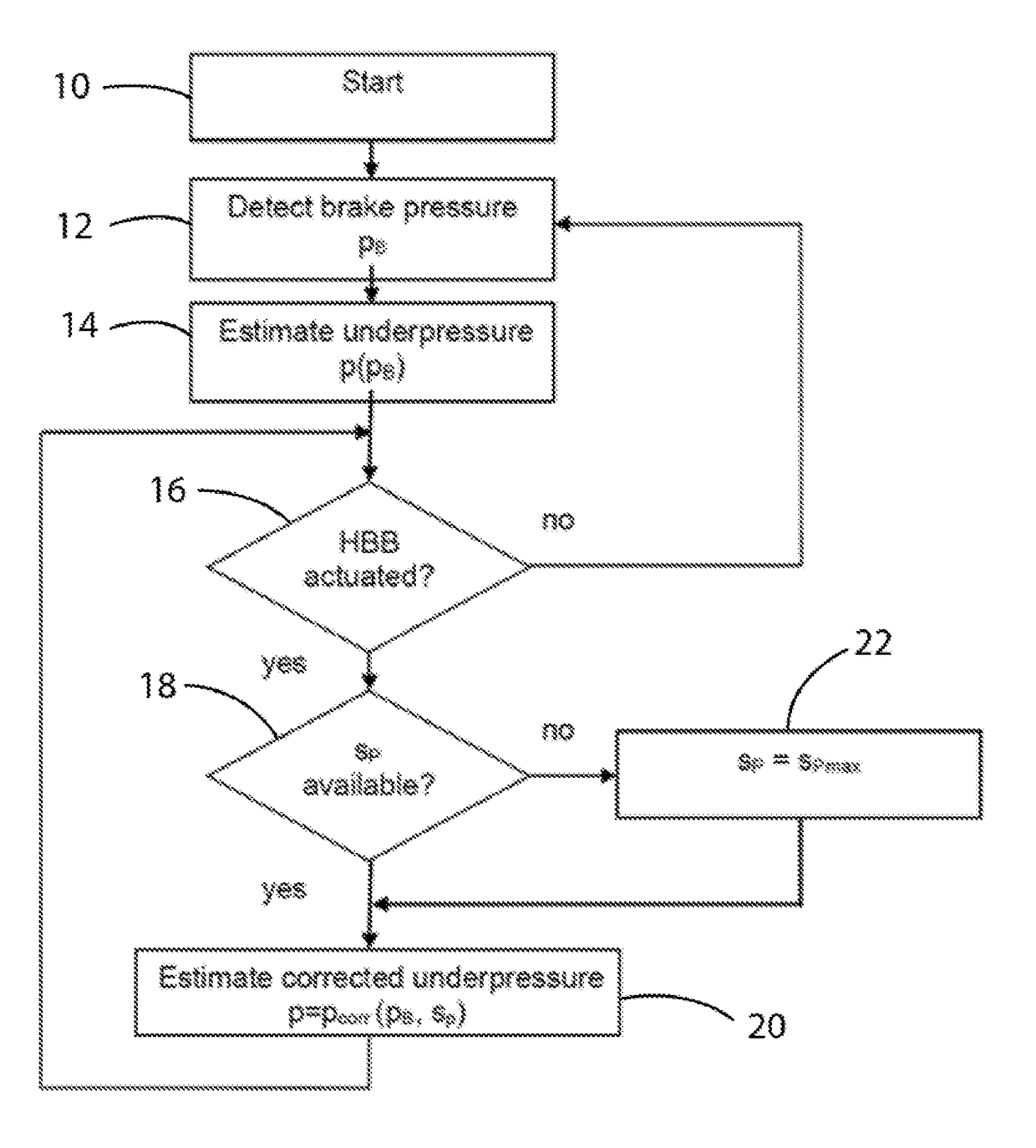
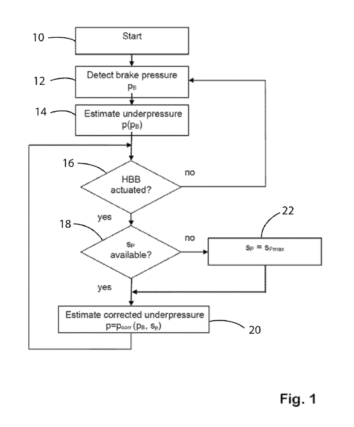
[0013]When the motor vehicle is operating and the driver activates the brake pedal and continuously increases the exerted brake pedal force, it results in an increase in the absolute air pressure in the working chamber caused by the changing position of the valve in the brake booster. This slightly reduces the underpressure prevailing in the underpressure chamber, i.e. the absolute pressure in the underpressure chamber increases slightly since the volume of the chamber shrinks because of the movement of the diaphragm while the number of air molecules initially remains the same.

[0014]If the increasing brake pressure exceeds a corresponding threshold value, the HBB actuates whereby a brake fluid pump of the vehicle movement dynamics control system pumps brake fluid from the master brake cylinder to the wheel brake cylin...


PUM


Abstract

A method for operating a hydraulic brake system of a motor vehicle having a brake booster and a hydraulic brake boost wherein a brake pressure is detected and an underpressure, prevailing in an underpressure chamber of the brake booster is estimated on the basis of the detected brake pressure. The hydraulic brake boost controlled based on the estimated underpressure, with the estimated underpressure taking into account an actuation of the hydraulic brake boost.

Description

CROSS-REFERENCE TO RELATED APPLICATIONS[0001]Not ApplicableBACKGROUND OF THE INVENTION1. Field of the Invention[0002]The invention relates to a method for operating a motor vehicle hydraulic brake system and, more particularly, for controlling a hydraulic brake booster.2. Description of Related Art[0003]Modern motor vehicles typically use a hydraulic brake system wherein a brake pedal activates a piston, connected to the brake pedal, of a master brake cylinder. The piston moves in a pressure chamber filled with brake fluid and generates a pressure, passed on via hydraulic lines, to at least one wheel brake device. The wheel brake device includes a wheel brake cylinder which, based on the pressure of the brake fluid, moves brake calipers with brake linings fitted thereon into abutment against a brake drum or a brake disk. The braking force acting on the wheel connected to the brake drum or brake disk generated and metered by activating the brake pedal. The master brake cylinder may b...

Claims


Application Information

Patent Timeline
IPC IPC(8): B60T8/44B60T8/171B60T8/172B60T13/16B60T7/04
CPCB60T8/441B60T8/171B60T8/172B60T13/166B60T7/042B60T13/662B60T8/442B60T13/46
Inventor MOORE, IANSCHMALER, CHRISTIANBAUMANN, MATTHIASSVENSSON, THOMAS
Owner FORD GLOBAL TECH LLC
Why Eureka
Try Eureka