Backlight module

a backlight module and backlight technology, applied in the field of backlight modules, can solve the problems of double-sided tape material cost and manual assembly time, and achieve the effect of reducing manufacturing costs

Inactive Publication Date: 2012-05-29
CHUNGHWA PICTURE TUBES LTD
View PDF9 Cites 2 Cited by
  • Summary
  • Abstract
  • Description
  • Claims
  • Application Information

AI Technical Summary

Benefits of technology

[0009]A backlight module that effectively reduces a manufacturing cost is provided in the present invention.
[0017]In light of the foregoing, the LEDs of the backlight module in the present invention have canopies; consequently, the problem of partial hot spots in the conventional backlight module is prevented and the light utilization rate is increased. In addition, the dispositions of canopies reduce the adoption of upper reflectors in the conventional backlight modules, thereby omitting the manufacturing cost and the assembling time.

Problems solved by technology

Hence, a material cost of the double-sided tape and a manual assembling time have to be consumed.

Method used


Image

  • Backlight module
  • Backlight module
  • Backlight module

Examples


first embodiment

[First Embodiment]

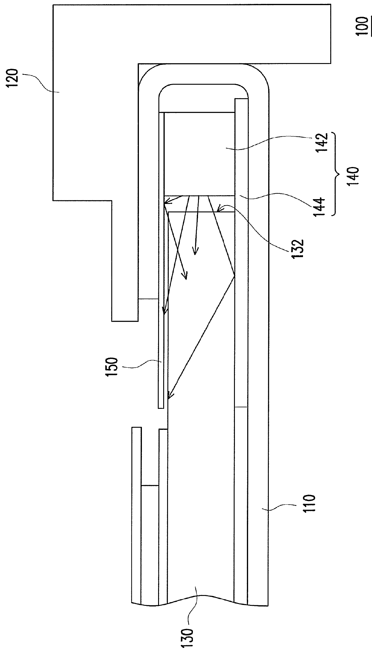
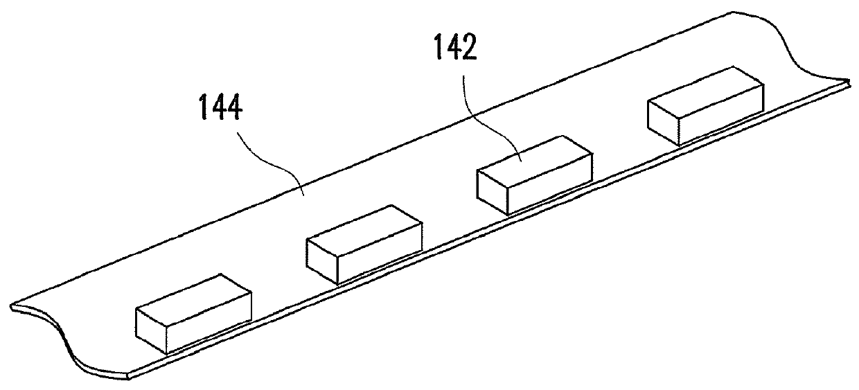
[0031]FIG. 3 is a schematic view illustrating a liquid crystal display (LCD) according to a first embodiment of the present invention. Referring to FIG. 3, a LCD 400 includes a backlight module 200 and a LCD panel 300, where the LCD panel 300 is disposed on the backlight module 200. The backlight module 200 includes a back plate 210, a frame 220, a light guide plate 230, and a light bar 240. The back plate 210 has a carrying portion 212 and at least one holding portion 214, and the frame 220 is leaned against the holding portion 214 of the back plate 210. The light guide plate 230 is disposed on the carrying portion 212 of the back plate 210, and one side of the light guide plate 230 is accommodated between the holding portion 214 and the carrying portion 212 of the back plate 210. The light bar 240 includes a flexible substrate 242 and a plurality of light emitting diodes (LEDs) 244. The flexible substrate 242 is disposed between the back plate 210 and the light g...

second embodiment

[Second Embodiment]

[0036]The present embodiment is approximately identical to the first embodiment, and same or similar reference numbers used in the present embodiment and in the first embodiment represent the same or similar elements. Accordingly, no further description thereof is provided hereinafter.

[0037]FIG. 4 is a schematic view illustrating a backlight module according to a second embodiment of the present invention. Referring to FIG. 4, different from the first embodiment, a flexible substrate 542 of a light bar 540 of a backlight module 500 in the present invention is parallel to the carrying portion 212 of the back plate 210. Also, the flexible substrate 542 is disposed between the light guide plate 230 and the carrying portion 212 of the back plate 210. In addition, a reflector 560 which is disposed between the light guide plate 230 and the back plate 210 extend to between the light guide plate 230 and the flexible substrate 542.

[0038]FIG. 5 is a schematic view of a ligh...

third embodiment

[Third Embodiment]

[0040]In both of the aforementioned embodiments, LEDs having first canopies are illustrated as exemplifications. However, those ordinarily skilled in the art can change the number and the disposing locations of canopies according to actual requirements.

[0041]FIG. 7A is a schematic diagram of the backlight module according to a third embodiment of the present invention. On the other hand, FIG. 7B is a schematic three-dimensional diagram of the LED in FIG. 7A. Similarly, same or similar reference numbers used in the present embodiment and in the aforementioned embodiments represent the same or similar elements. Accordingly, no further description thereof is provided hereinafter. Referring to FIG. 7A and FIG. 7B simultaneously, a plurality of LEDs 644 of a light bar 640 of a backlight module 600 each has a first canopy 646 and a second canopy 648. The first canopy 646 is disposed between the top portion 214a of the holding portion 214 and the light guide plate 230. Th...


PUM


Abstract

A backlight module including a back plate, a frame, a light guide plate, and a light bar is provided. The back plate has a carrying portion and at least one holding portion, and the frame is leaned against the holding portion. The light guide plate is disposed on the carrying portion of the back plate, and one side of the light guide plate is accommodated between the holding portion and the carrying portion. The light bar includes a flexible substrate and a plurality of light emitting diodes (LEDs). The flexible substrate is disposed between the back plate and the light guide plate. The LEDs are disposed on the flexible substrate and located on the carrying portion of the back plate and by the light guide plate. Each of the LEDs has a first canopy which is located between the carrying portion and the light guide plate.

Description

CROSS-REFERENCE TO RELATED APPLICATION[0001]This application claims the priority benefit of Taiwan application serial no. 98206337, filed on Apr. 16, 2009. The entirety of the above-mentioned patent application is hereby incorporated by reference herein and made a part of specification.BACKGROUND OF THE INVENTION[0002]1. Field of Invention[0003]The present invention relates to a backlight module, and more particularly to a backlight module which can reduce manufacturing cost.[0004]2. Description of Related Art[0005]With advancements in semiconductor industry and relevant electronic industries, digital devices such as mobile phones, digital cameras, digital video cameras, notebooks, and desktop computers have made progress to meet requirements for easy operation, multiple functionality, and attractive exterior design. However, using IT products as described above demands a suitable display screen acting as a man-machine interface, and the display screens of the products aforementione...

Claims


Application Information

Patent Timeline
Patent Type & Authority Patents(United States)
IPC IPC(8): G09F13/04
CPCG02F1/133308G02F1/133615
Inventor HO, CHUNG-HSING
Owner CHUNGHWA PICTURE TUBES LTD
Why Eureka
Try Eureka