Rotor hub, spindle motor and hard disk drive

a technology of rotor hub and spindle motor, which is applied in the direction of record information storage, instruments, transportation and packaging, etc., can solve the problems of reducing cutting quantity, insufficient stably supporting hard disks, and reducing cutting efficiency, so as to restrain the breakage of the rotor hub, and reduce the separation of inclusions.

Inactive Publication Date: 2012-05-29
TOKUSEN IND CO LTD +1
View PDF12 Cites 0 Cited by
  • Summary
  • Abstract
  • Description
  • Claims
  • Application Information

AI Technical Summary

Benefits of technology

[0009]In view of the above, the present invention provides a rotor hub that can be formed in a cost-effective manner and with increased accuracy.
[0011]As a result, the inclusions present in the top panel portion are obliquely laid down or crushed into a small size, which restrains the inclusions from being separated from the top panel portion. Moreover, even when the top panel portion has an extremely thin region, it is possible to prevent the inclusions from penetrating that region. Separation of the inclusions is further restrained by removing the superficial layer. In order to obtain such a rotor hub, upsetting is performed particularly on the top panel portion during the plastic working with an upsetting percentage of 30% to 70%. By doing so, it is possible to restrain breakage of the rotor hub during the plastic working and to control the orientation of the inclusions present in the top panel portion. This makes it possible to reduce separation of the inclusions and to prevent contamination of the surfaces of hard disks.
[0012]Separation of the inclusions present in the disk mounting surface can also be reduced by allowing the inclusions to extend obliquely with respect to the disk mounting surface. Since a disk comes into direct contact with the disk mounting surface, it is more preferable to reliably restrain separation of the inclusions by inclining the inclusions at 45 degrees or more.
[0013]With the present invention, use of the free-cutting stainless steel as a raw material of the rotor hub makes it easy to perform a cutting operation after forging. This improves working accuracy without reduction in productivity. In case of forming an article by forging or pressing, it is typical that free-cutting stainless steel is not used because priority is given to formability. In the present invention, however, free-cutting stainless steel is used in consideration of the cutting operation after forging. Use of the free-cutting stainless steel requires some conditions to the forging and makes the forging more difficult to perform than a typical one. Nevertheless, the cutting operation after forging becomes easy to perform, thus increasing the productivity as a whole and eventually reducing the manufacturing costs.
[0014]It is one of the features of the present invention that, after forging or pressing, the rotor hub is annealed at a temperature higher than the recrystallization temperature. The annealing induces recrystallization of the rotor hub and removes residual stresses generated in the course of plastic working. Recrystallization improves machinability of the rotor hub. The machinability is further increased if the annealing temperature is in a range of from 700° C. to 830° C.
[0016]One example of free-cutting stainless steel for use in producing the bar having elongated inclusions includes ferritic free-cutting stainless steel containing P, Mn, S and Cu of specified content ranges. In these content ranges, elongated inclusions are easily formed. Furthermore, the ferritic free-cutting stainless steel of these content ranges is relatively hard to crack and therefore can be easily forged or pressed.

Problems solved by technology

No matter how accurate the bearing is, that alone is not sufficient to stably support the hard disks 14.
However, cutting is costly to perform.
With the two conventional methods mentioned above, it is possible to reduce the cutting quantity of a material but it is not easy to perform the cutting operation after the forging work.
In particular, it is difficult to secure the accuracy of a disk mounting surface.
If the free-cutting stainless steel is merely used in the two conventional methods, it is often the case that the stainless steel is cracked during the forging process.
Furthermore, since the rotor hub is manufactured by plastic working, there is a fear that inclusions contained in the free-cutting stainless steel become easily separable.
Such adherence of the inclusions is not permitted because the surfaces of the hard disks need to be kept clean.

Method used


Image

  • Rotor hub, spindle motor and hard disk drive
  • Rotor hub, spindle motor and hard disk drive
  • Rotor hub, spindle motor and hard disk drive

Examples


example

1. Status of Inclusions in the Present Rotor Hub

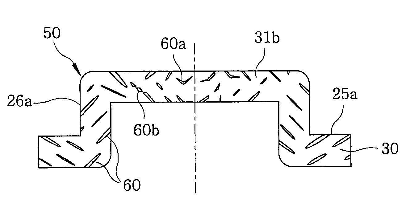
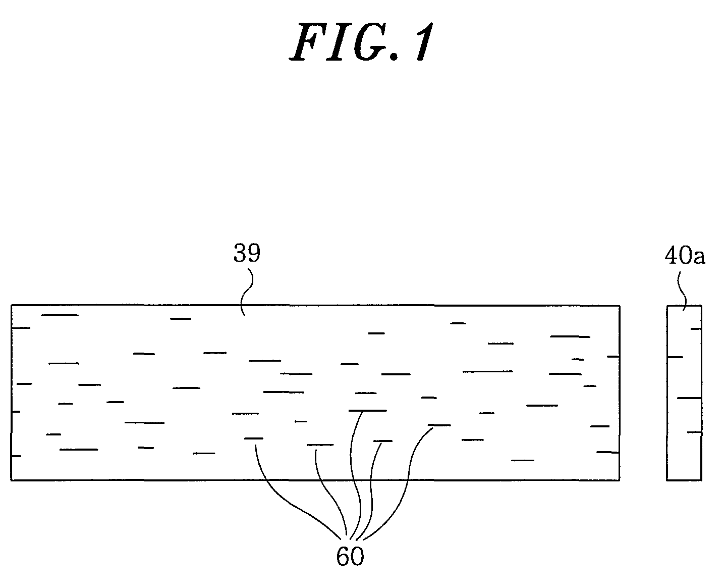
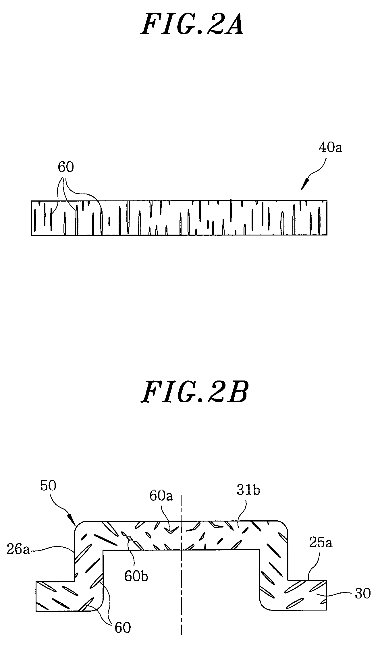
[0062]The intermediate member 50 of the present invention, the shape of inclusions appearing in the cross section thereof and an actual example of the inclusion inclining method will be described with reference to FIGS. 4 through 9.

[0063]FIG. 4A shows an overall cross-sectional shape of the intermediate member 50. An annular surface 25a that would become a disk mounting surface after a finishing work is formed on a disk mounting portion 30. Also formed is a cylindrical surface 26a that would become a cylindrical disk fitting surface after the finishing work. FIG. 4A is a sectional view obtainable by sectioning the intermediate member 50 along a plane including the center axis of the annular surface 25a. In FIG. 4A, areas A, B and C designate a region corresponding to the top panel portion 31 of the intermediate member, a region just below the cylindrical disk fitting surface 26a of the intermediate member and a region just below the di...


PUM

PropertyMeasurementUnit
sizeaaaaaaaaaa
thicknessaaaaaaaaaa
lengthaaaaaaaaaa

Abstract

In a method for manufacturing a rotor hub for use in a spindle motor, free-cutting stainless steel is used as a material of the rotor hub. A slug of free-cutting stainless steel is subjected to a plastic working to form a disk mounting portion and a cylindrical surface positioned radially inwardly of the disk mounting portion. Then, a cylindrical disk fitting surface is formed by machining substantially the entirety of the cylindrical surface. The rotor hub contains A-type inclusions appearing in a cross section taken along a center axis of the disk mounting portion. The A-type inclusions are oriented in directions different than the center axis.

Description

FIELD OF THE INVENTION[0001]The present invention relates to a spindle motor for use in a hard disk drive and, more particularly, to a rotor hub, one of major parts of the spindle motor.BACKGROUND OF THE INVENTION[0002]A hard disk drive was originally developed as a storage device of a computer. In recent years, however, the hard disk drive is extensively employed not only in the computer but also in home electric appliances such as a video recorder, a portable music player and a camcorder.[0003]Expansion of use of the hard disk drive is sustained by the increased storage capacity and the reduced price. The storage capacity of a hard disk drive has been increased one hundred times for the last decade, whereas the price thereof has been decreased steadily. There is a strong demand for a device capable of storing enormous information in a cost-effective manner, which tendency is expected to last in the future. Under the circumstances, high accuracy and low price are all required in ea...

Claims


Application Information

Patent Timeline
Patent Type & Authority Patents(United States)
IPC IPC(8): G11B17/08G11B17/02
CPCB21J1/025B21J1/04G11B19/2009B21K1/32Y10T29/49025B21K1/40B23P13/02H02K5/04
Inventor MIYAUCHI, TOSHIAKIYAMAMOTO, YASUO
Owner TOKUSEN IND CO LTD
Why Eureka
Try Eureka