Portable fluorescent lighting system with long-life hinge mechanism

a fluorescent lighting and hinge mechanism technology, applied in lighting applications, lighting support devices, light source combinations, etc., can solve the problems of failure of the wire, difficulty in improving the retention mechanism the given life of the hinge mechanism, etc., to achieve low cost, low cost, and robust manipulation

Inactive Publication Date: 2012-06-05
KINO FLO
View PDF5 Cites 0 Cited by
  • Summary
  • Abstract
  • Description
  • Claims
  • Application Information

AI Technical Summary

Benefits of technology

[0007]The present invention addresses the issue of hinge wire maintenance by presenting a low cost high-tension mechanical retention hinge while not adding weight. The hinge construction takes into account the off center pivot point of the panels. It is designed for robust manipulation, low cost, ease of manufacturing and long tension life. It is designed for easy field replacement should the necessity ever arise.

Problems solved by technology

The hinge retention mechanism being made of flexible metal wire had a given life span due to metal fatigue.
After the metal fatigue resulted in the failure of the wire it would have to be replaced.
Attempts at improving on the wire retention mechanism were challenging in that the panels do not pivot on a central point.
Applying conventional hinges to the fixture design never worked due to the pivot centers always being off center.
Replacing the living hinge with a conventional hinge dramatically increased the cost and weight of the fixture as well as assembly costs.
There was never a viable solution to improving on the hinge.
Film Gear, a Chinese manufacturer constructed a mechanism that comprised many parts that added weight and was costly to construct.
Over time this tension would lessen and fail to support the panels.
The high assembly cost, weight and limited mobility of the mechanism were not considered a product enhancement.
The performance of this hinge over time did not live up to the claims of superiority.
When it required replacement the process was also labor intensive.
This approach never found market acceptance.

Method used


Image

  • Portable fluorescent lighting system with long-life hinge mechanism
  • Portable fluorescent lighting system with long-life hinge mechanism
  • Portable fluorescent lighting system with long-life hinge mechanism

Examples


Embodiment Construction

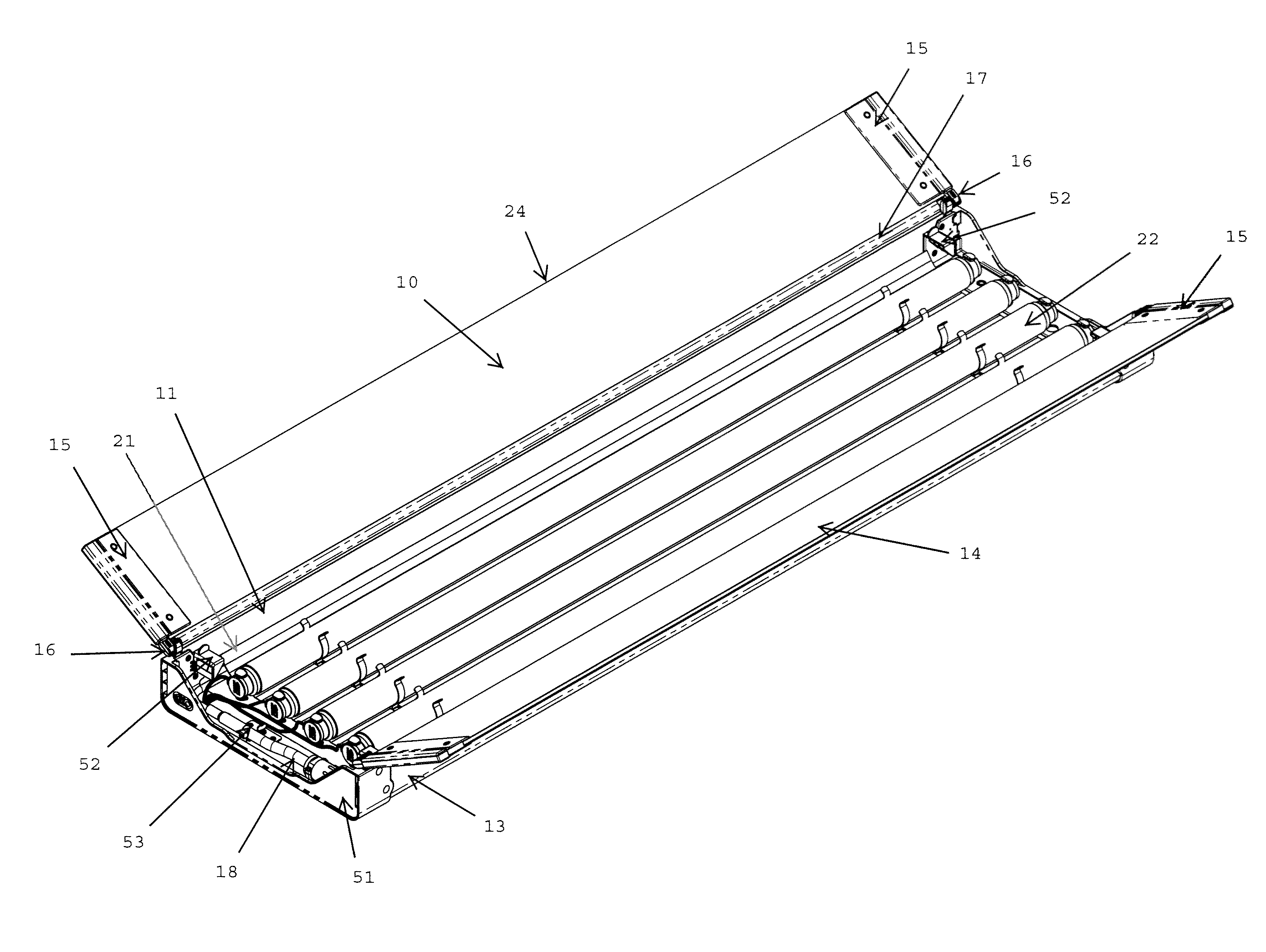
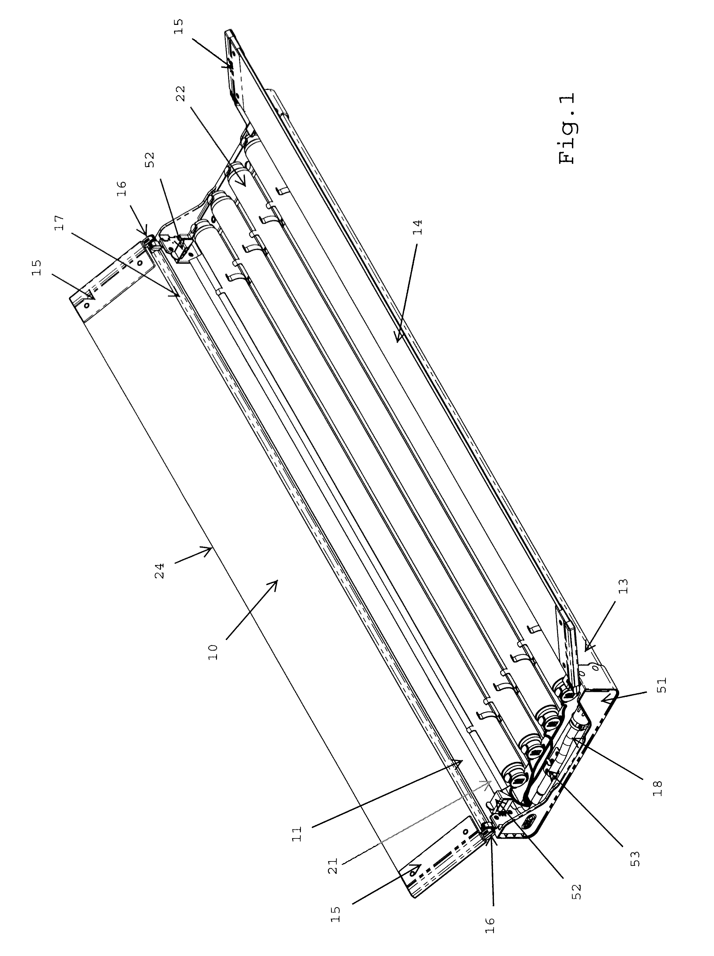
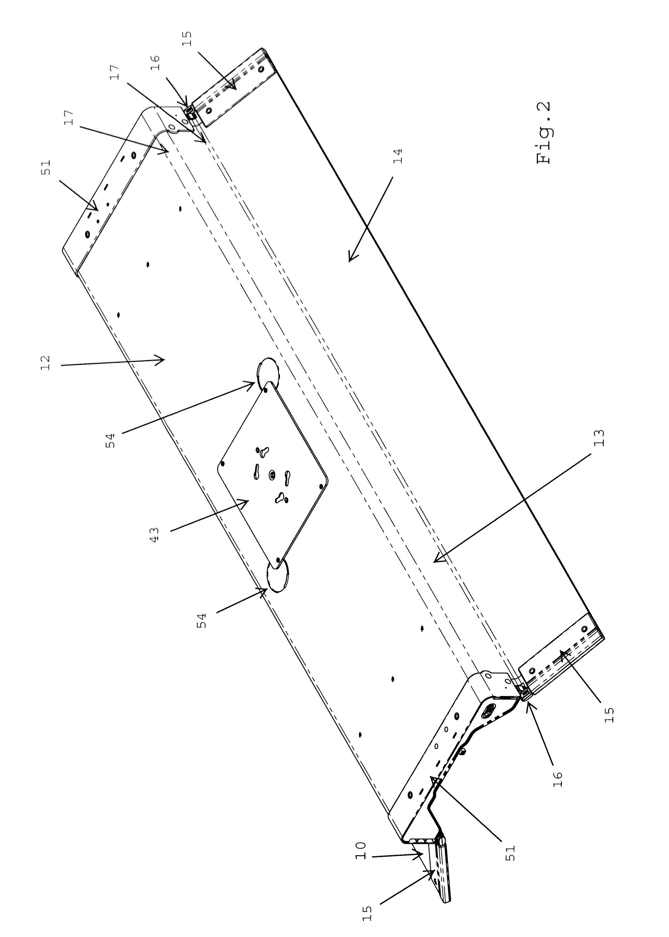
[0026]Referring to the figures in detail, FIGS. 1 and 2 are perspective views of the present invention. The invention comprises an elongated corrugated plastic panel 24 made into five subpanels by removing three flutes 17 (only one is shown) of the corrugation out to provide for hinging. The panel 24 includes center panel 12 at the center of said panel, a pair of inner subpanels 11 and 13 each on one side of center subpanel 12, outer subpanel 10 positioned on the outer side of inner subpanel 11, and outer subpanel 14 positioned on outer side of inner subpanel 13. All subpanels 10, 11, 13 and 14 are symmetrically positioned and longitudinally extending in parallel to center subpanel 12. Removal of two flutes 17 at each juncture of subpanels 10 / 11 and 13 / 14 provide for convenient and flexible hinging of subpanels without adding extra weight. The center panel may be reflective or an aluminum or other reflective material 21 may be placed under the lamps.

[0027]In order to prevent the sub...


PUM


Abstract

A hinge retaining mechanism for a fluorescent lighting system. A portable fluorescent lighting system which utilizes an extremely lightweight corrugated plastic panel made into 5 subpanels. At each end of the panel a U shaped channel is attached that forms the center panel and the opposing adjacent two panels into a trough or recessed pan. On each of the two remaining panels is attached another U shaped channel. Each of the U shaped channels includes a mechanism for supporting a high-tension mechanical hinge. The mechanical hinge is designed to float freely within the adjacent channel brackets. One part of the hinge is mechanically retained to the channel to prevent inadvertent removal of the hinge.

Description

BACKGROUND OF THE INVENTION[0001]1. Field of the Invention[0002]This invention relates to a portable and lightweight fluorescent lighting system suitable for use in the field of photography, television and motion pictures utilizing fluorescent lamps.[0003]2. Description of the Prior Art[0004]U.S. Pat. No. 5,132,885 disclosed a portable fluorescent lighting system. This system comprised of 5 corrugated panels that formed the basis of a lighting fixture. The five panels were created from one piece of corrugated polypropylene plastic. The panels were established by removing two to three upright flutes and one skin of corrugation between each panel. The remaining material formed a living hinge joining the 5 panels. The ends of the panel contained a U channel that carried a flexible metal wire that acted as a retention mechanism for holding the orientation of the panels once they were positioned by the user. The lighting system became very popular in motion picture lighting applications....

Claims


Application Information

Patent Timeline
Patent Type & Authority Patents(United States)
IPC IPC(8): F21V21/00
CPCF21V7/18F21V11/00F21V14/08F21V17/007F21V17/06F21Y2113/00F21W2131/406F21Y2103/00
Inventor VAZQUEZ, ALEJANDROHOCHHEIM, FRIEDER
Owner KINO FLO
Why Eureka
Try Eureka