Catheter with multiple ultrasound radiating members

a catheter and ultrasound technology, applied in the field of ultrasonic catheters, can solve the problems of difficult design of ultrasonic catheters capable of efficiently applying ultrasound energy over such lengths, and affecting the efficiency of ultrasound energy application

Active Publication Date: 2012-06-05
EKOS CORP
View PDF357 Cites 22 Cited by
  • Summary
  • Abstract
  • Description
  • Claims
  • Application Information

AI Technical Summary

Benefits of technology

[0011]Another solution for emitting ultrasonic energy over such lengths is to provide the ultrasonic catheter with a plurality of ultrasonic transducers spaced along a distal region of the catheter. Such an arrangement faces several technical hurdles. For example, because the ultrasonic transducers are relatively rigid, the catheter may become too inflexible to be navigated through the lumens of the patient's body. One solution is to use smaller transducers as disclosed in U.S. Patent Publication No. 2004 / 0024347, published Feb. 5, 2004, the entirety of which is incorporated by reference herein. In this publication, a catheter is disclosed which can utilize sixty ultrasound radiating members 40 arranged in pairs. The 30 pairs of ultrasound radiating members can be spaced over a length of approximately 30 to 50 cm and arranged in groups. However, within these broad ranges there is a need to select the number and spacing which balances the need to provide enhanced bioefficacy while reducing or minimizing the number of ultrasound radiating members. In general, it would be desirable to reduce or minimize the number or ultrasound radiating members while substantially maintaining bioefficacy so as to reduce the parts and cost of the catheter and improve the overall flexibility of the catheter.

Problems solved by technology

To date, it has been difficult to design an ultrasonic catheter capable of efficiently applying ultrasound energy over such lengths.
However, this arrangement is generally undesirable because it requires a translation system for moving the ultrasonic elements within the catheter.
Such an arrangement faces several technical hurdles.
For example, because the ultrasonic transducers are relatively rigid, the catheter may become too inflexible to be navigated through the lumens of the patient's body.

Method used


Image

  • Catheter with multiple ultrasound radiating members
  • Catheter with multiple ultrasound radiating members
  • Catheter with multiple ultrasound radiating members

Examples


Embodiment Construction

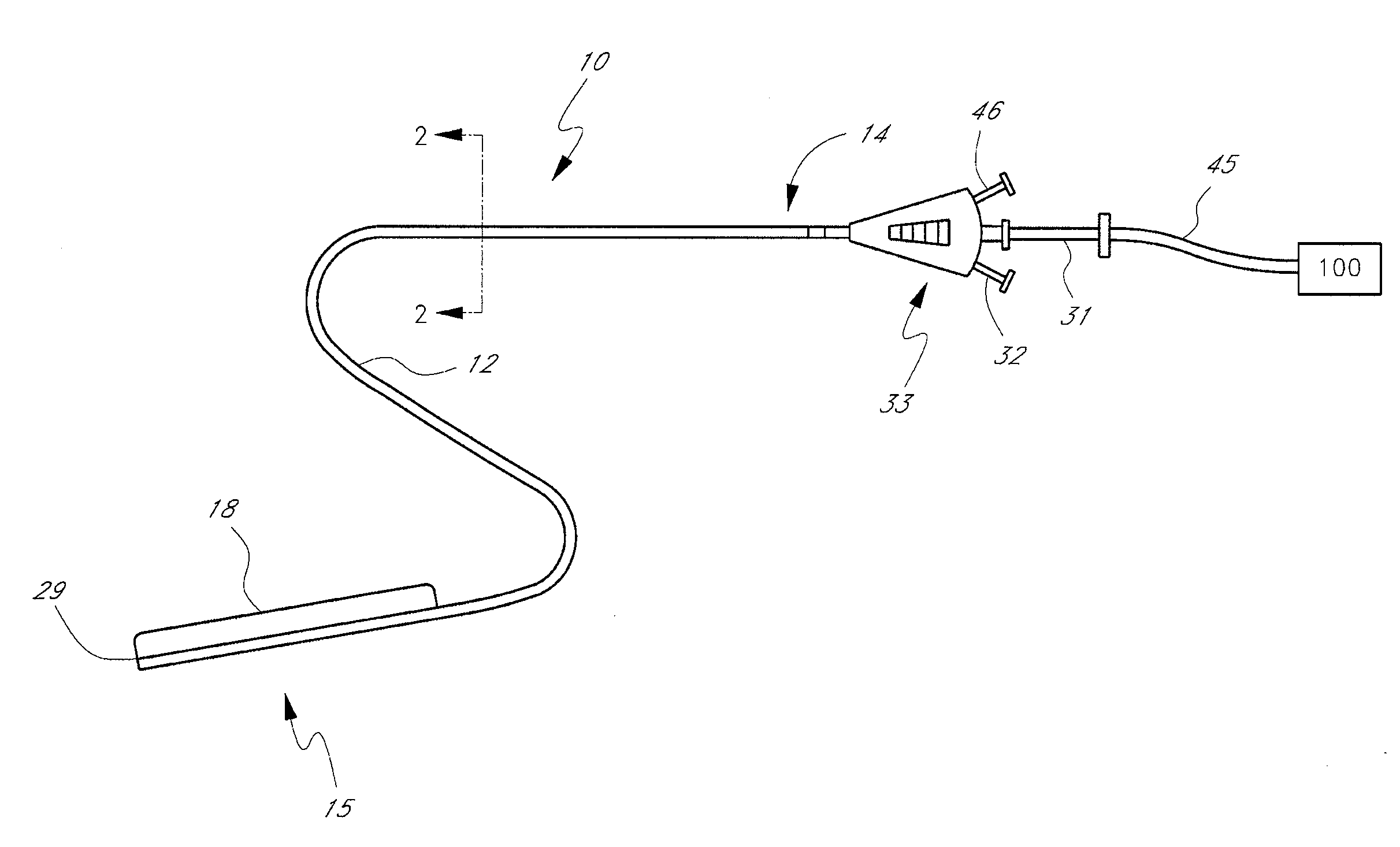
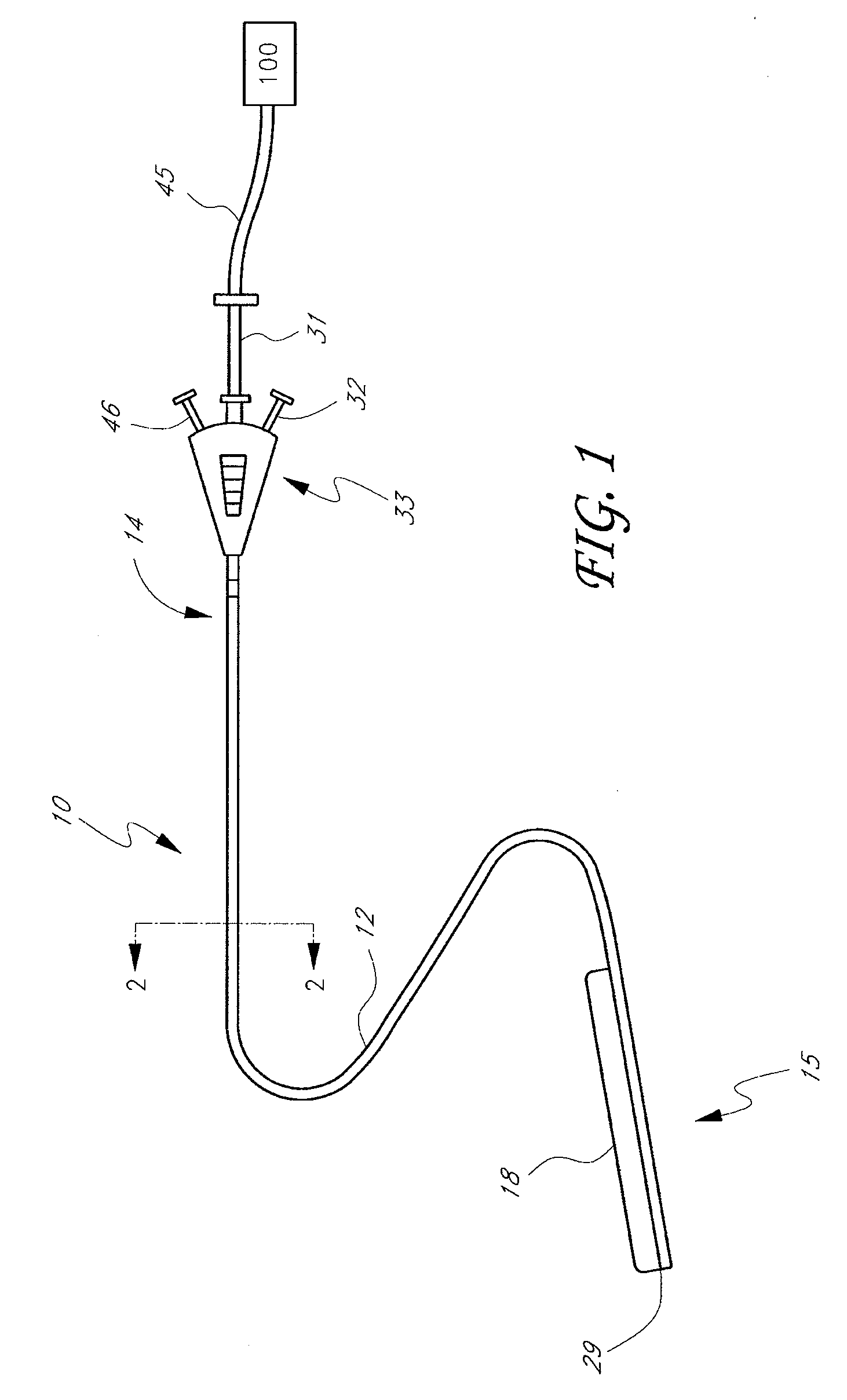
[0051]As described above, it is desired to provide an ultrasonic catheter having various features and advantages. Examples of such features and advantages include the ability to apply ultrasonic energy to a treatment site. In another embodiment, the catheter has the ability to deliver a therapeutic compound to the treatment site. Preferred embodiments of an ultrasonic catheter having certain of these features and advantages are described herein. Methods of using such an ultrasonic catheter are also described herein.

[0052]The ultrasonic catheters described herein can be used to enhance the therapeutic effects of therapeutic compounds at a treatment site within a patient's body. As used herein, the term “therapeutic compound” refers broadly, without limitation, to a drug, medicament, dissolution compound, genetic material or any other substance capable of effecting physiological functions. Additionally, any mixture comprising any such substances is encompassed within this definition o...


PUM


Abstract

A catheter system for delivering ultrasonic energy to a treatment site includes a tubular body having a proximal end, a distal end and a treatment zone located between the distal end and the proximal end. An ultrasonic assembly is positioned within the treatment zone and provides providing an average longitudinal power density between about 0.2 and about 1.0 W / cm within the treatment zone.

Description

CROSS-REFERENCE TO RELATED APPLICATIONS[0001]This application claims the priority benefit to U.S. Provisional No. 60 / 855,172 filed Oct. 27, 2006, the entirety of which is hereby incorporated by reference herein.BACKGROUND OF THE INVENTION[0002]1. Field of the Invention[0003]The present invention relates generally to an ultrasonic catheter and more specifically to an ultrasonic catheter configured to deliver ultrasonic energy and a therapeutic compound to a treatment site.[0004]2. Description of the Related Art[0005]Several medical applications use ultrasonic energy. For example, U.S. Pat. Nos. 4,821,740, 4,953,565 and 5,007,438 disclose the use of ultrasonic energy to enhance the effect of various therapeutic compounds. An ultrasonic catheter can be used to deliver ultrasonic energy and a therapeutic compound to a treatment site in a patient's body. Such an ultrasonic catheter typically includes an ultrasound assembly configured to generate ultrasonic energy and a fluid delivery lum...

Claims


Application Information

Patent Timeline
Patent Type & Authority Patents(United States)
IPC IPC(8): A61B8/00
CPCA61N7/022A61B17/2202A61N2007/0078
Inventor SOLTANI, AZITAWILCOX, ROBERT L.
Owner EKOS CORP
Why Eureka
Try Eureka