Antenna apparatus

a technology of antenna and antenna body, which is applied in the direction of antenna earthing, substantially flat resonant elements, resonant antennas, etc., can solve the problems of difficult to apply monopole antennas to apparatuses and difficult to achieve further low profile, etc., and achieves a wider band, low profile, and reduced size

Active Publication Date: 2012-06-05
HITACHI KOKUSAI YAGI SOLUTIONS +1
View PDF35 Cites 20 Cited by
  • Summary
  • Abstract
  • Description
  • Claims
  • Application Information

AI Technical Summary

Benefits of technology

[0010]The present invention has been made to solve the abovementioned problem and an object thereof is to provide an antenna apparatus which realizes size reduction and low profile, and wider band.

Problems solved by technology

However, since the abovementioned conventional monopole antenna must have a height of at least about ¼ wavelength and it is difficult to achieve further low profile, it is undesirable as a relay antenna installed in an underground mall or the like.
A monopole antenna can obtain excellent characteristics in a single frequency band, but it basically corresponds to a narrow band and its specific bandwidth in a region where VSWR (voltage standing wave ratio) is low, for example, 2 or less is generally about ten and several percentages, so that it is difficult to apply the monopole antenna to an apparatus which performs bulk transmission according to a wideband communication.

Method used


Image

  • Antenna apparatus
  • Antenna apparatus
  • Antenna apparatus

Examples


first embodiment

[0119

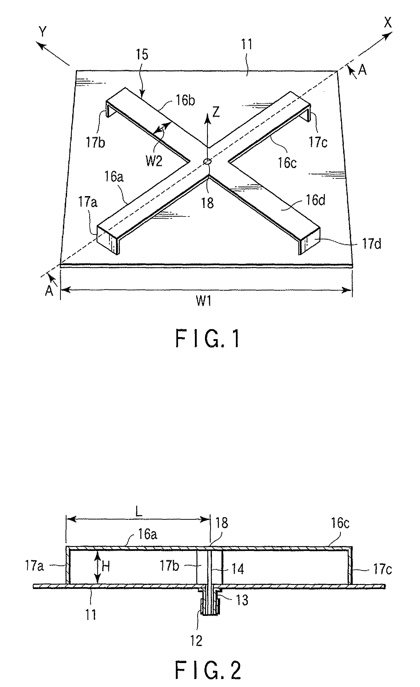
[0120]FIG. 1 is a perspective view showing a basic configuration of an antenna apparatus according to the present invention. FIG. 2 is a sectional view of the antenna apparatus taken in a direction of arrows A-A in FIG. 1.

[0121]In FIG. 1 and FIG. 2, a conductor plate 11 is formed using, for example, a square grounding plate and a length W1 of one side thereof is set to about 0.5λL or more (λL represents a wavelength of the lowest frequency in a working frequency band).

[0122]A coaxial connector 12 of, for example, NJ type is attached to a central portion of a lower of the conductor plate 11 as a feeding terminal. The coaxial connector 12 is connected with a coaxial cable for feeding extending from an antenna input circuit of a radio unit (not shown). The coaxial connector 12 is provided with an outer conductor 13 and a central conductor 14. The outer conductor 13 is electrically connected to the conductor plate 11. The central conductor 14 is provided to extend through a through...

second embodiment

[0134

[0135]Next, an antenna apparatus according to a second embodiment of the present invention will be explained.

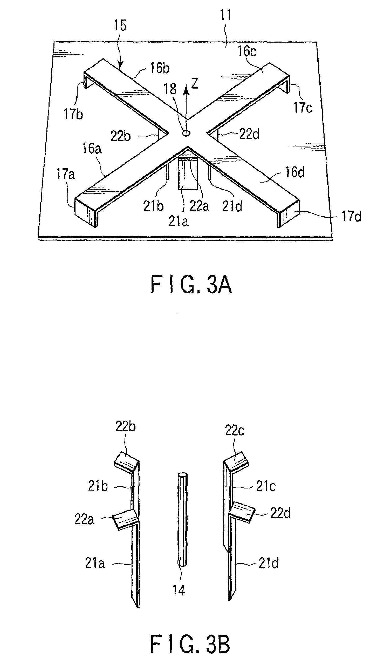
[0136]FIG. 3A is a perspective view of an antenna apparatus according to the second embodiment of the present invention, FIG. 3B is a perspective view showing a main portion (a passive element portion), and FIG. 4 is a side view of the antenna apparatus. Incidentally, same portions as those in the first embodiment are attached with same reference numerals and detailed explanation thereof is omitted.

[0137]The second embodiment has such a configuration that at least one, for example, four matching passive elements 21a to 21d are provided at equal intervals (at equal angles) on a concentric circle of a feeding portion, namely, the central conductor 14 of the coaxial connector 12 protruded above the conductor plate 11 in the antenna apparatus according to the first embodiment.

[0138]By arranging the passive elements 21a to 21d near the central conductor 14, electromagnetic co...

third embodiment

[0149

[0150]Next, an antenna apparatus according to a third embodiment of the present invention will be explained.

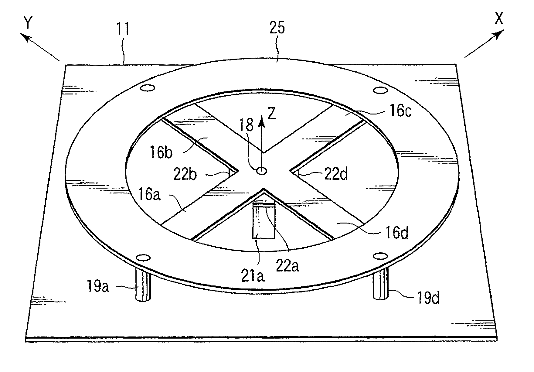
[0151]FIG. 13 is a perspective view of an antenna apparatus according to the third embodiment of the present invention.

[0152]The third embodiment has such a configuration that the antenna apparatus according to the second embodiment is further provided with line paths connecting end portions of adjacent ones of the radiating elements 16a to 16d. As seen in FIG. 13, the radiating elements 16a to 16d extend radially from the feeding portion at equal circumferentially spaced intervals. The third embodiment is configured such that excellent impedance characteristic is obtained over wider band, for example, by providing a ring-shaped element 25 on upper portions of the radiating elements 16a to 16d in parallel with the conductor plate 11.

[0153]Incidentally, in the third embodiment, short pins 19a to 19d are used instead of the short-circuiting elements 17a to 17d shown in the ...


PUM


Abstract

An aspect of an antenna apparatus according to the present invention is provided with a conductor plate, radiating elements disposed to face the conductor plate and partially short-circuited to the conductor plate, a feeding terminal provided on the conductor plate, and a feeding path connecting the feeding terminal and a feeding portion of the radiating elements to each other.

Description

CROSS REFERENCE TO RELATED APPLICATIONS[0001]This is a Continuation Application of PCT Application No. PCT / JP2007 / 066480, filed Aug. 24, 2007, which was published under PCT Article 21(2) in Japanese.[0002]This application is based upon and claims the benefit of priority from prior Japanese Patent Applications No. 2006-228197, filed Aug. 24, 2006; and No. 2007-029438, filed Feb. 8, 2007, the entire contents of both of which are incorporated herein by reference.BACKGROUND OF THE INVENTION[0003]1. Field of the Invention[0004]The present invention relates to an antenna apparatus used in a relay unit.[0005]2. Description of the Related Art[0006]As an antenna for relay which re-transmits ground wave for a mobile phone, television broadcast, or the like to a blind zone such as an underground mall, a small-sized and weight-reduced antenna is demanded in view of a problem about an installation place, aesthetic purposes or the like. As an antenna for relay, vertical polarized and horizontal-p...

Claims


Application Information

Patent Timeline
Patent Type & Authority Patents(United States)
IPC IPC(8): H01Q1/38H01Q5/25H01Q5/385H01Q5/40
CPCH01Q1/007H01Q9/045H01Q9/0457H01Q9/40H01Q5/40H01Q21/205H01Q5/25H01Q5/385H01Q9/46H01Q13/08H01Q5/00H01Q9/16
Inventor FUJITA, SEIKENNAKANO, HISAMATSUWAKO, IICHITANAKA, KENUMEGAKI, TOSHIHITO
Owner HITACHI KOKUSAI YAGI SOLUTIONS
Why Eureka
Try Eureka