

Endoscope apparatus
a technology of endoscope and endoscope, which is applied in the direction of emergency protective arrangements for limiting excess voltage/current, instruments, applications, etc., and can solve problems such as induced explosions
- Summary
- Abstract
- Description
- Claims
- Application Information
AI Technical Summary
Benefits of technology
Problems solved by technology
Method used
Image

Examples
first embodiment
(1) First Embodiment
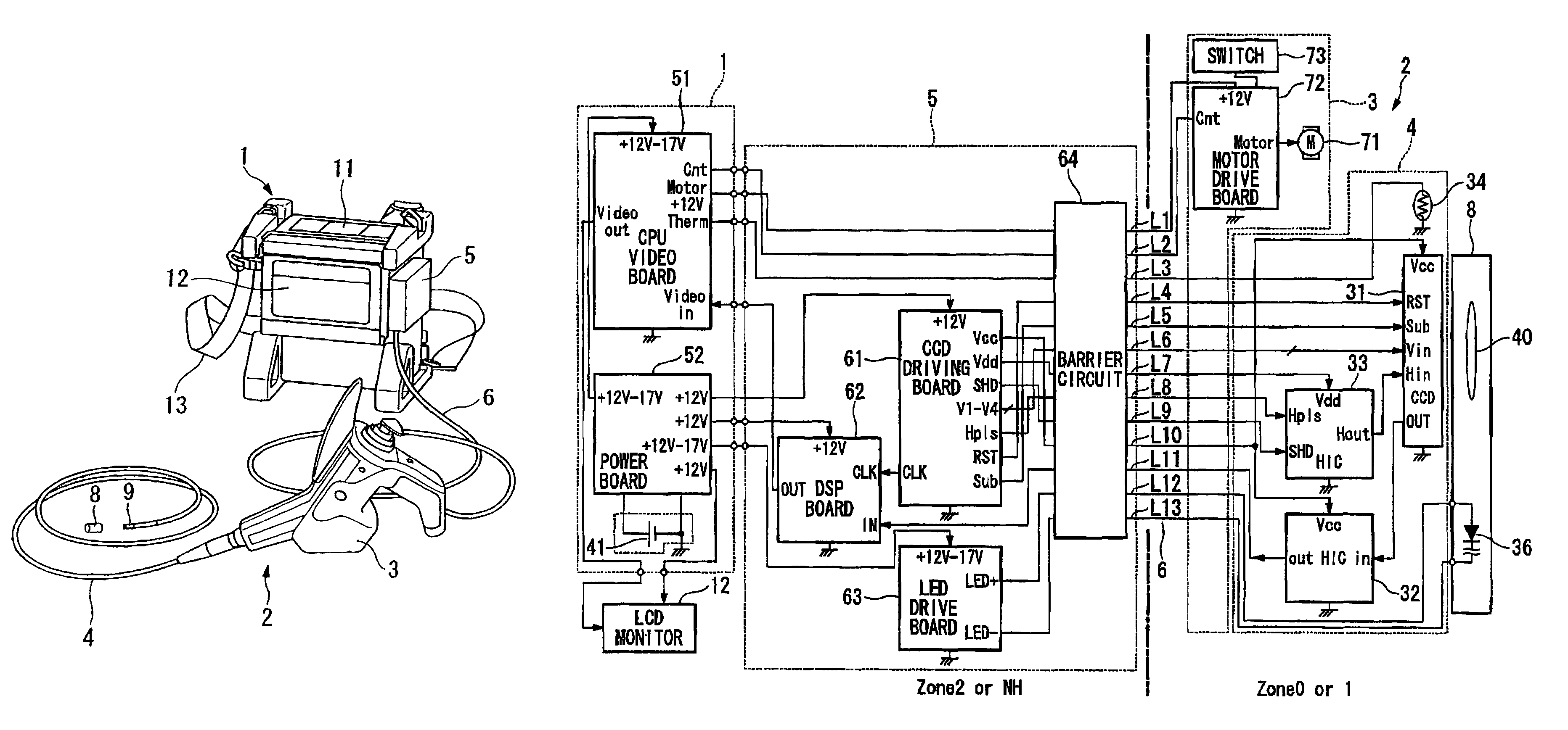
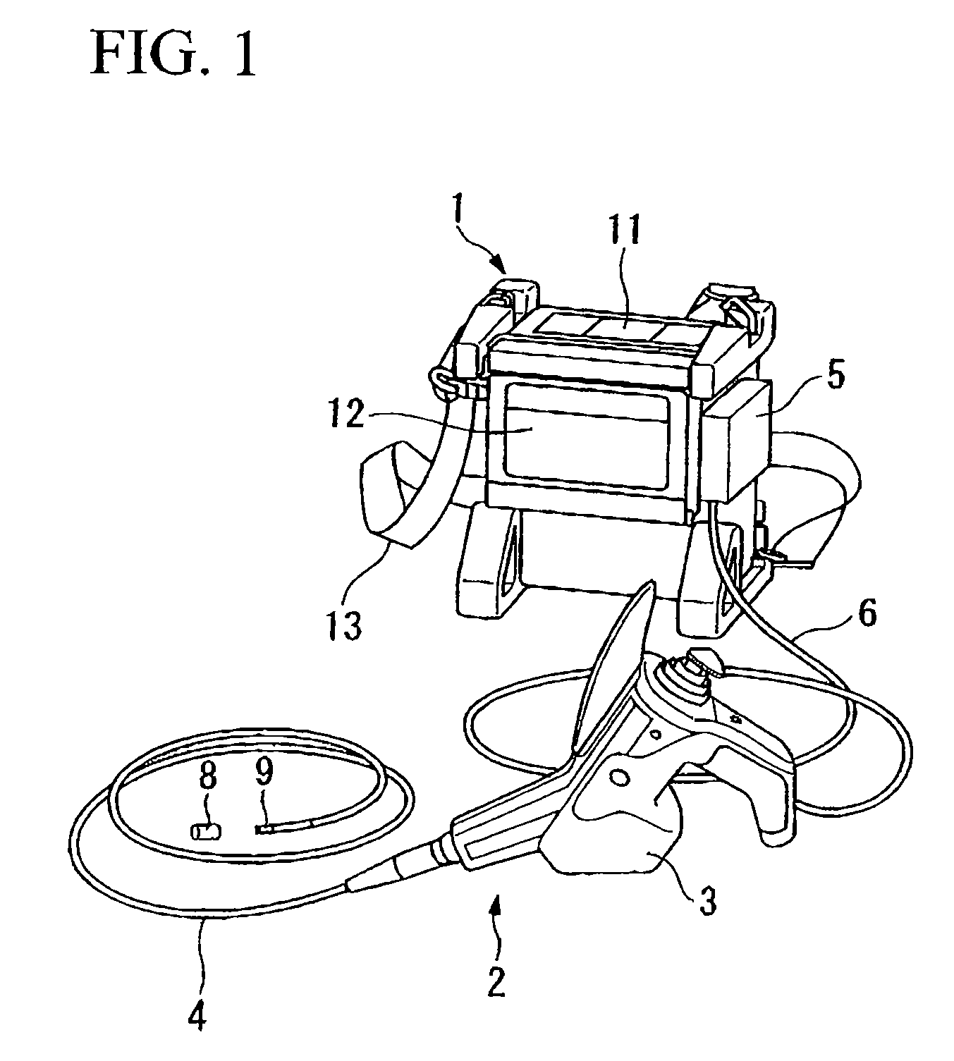
[0050]FIG. 1 is a general view of the endoscope apparatus according to the first embodiment of the present invention. In FIG. 1, a main unit 1 governs controlling an entire endoscope apparatus. A front panel 11 for carrying out various setups is disposed on a top surface of the main unit 1. An LCD monitor 12 for displaying a monitored image is attached on one of side surfaces of the main unit 1. A belt 13 can be attached to the main unit 1 so that it is carried on the shoulder of a user and hands-free operation can be conducted by the user.
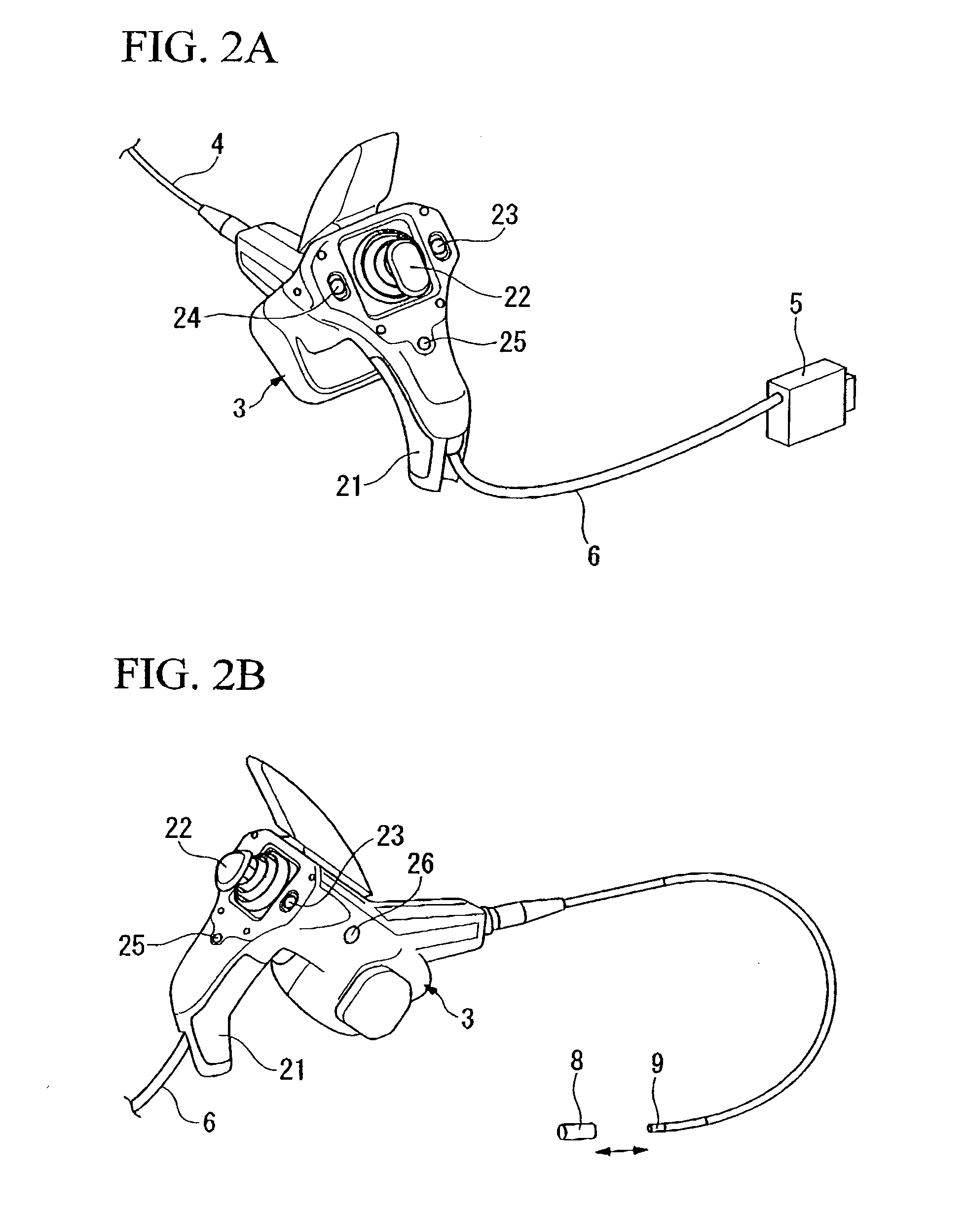
[0051]A scope unit 2 is formed by a control unit 3, an insertion portion 4 attached to the control unit 3, and an optical adaptor 8 detachably attached to a tip of the insertion portion 4. The control unit 3 is attached to the main unit 1 detachably via a scope connector 5. As explained later, in the first embodiment of the present invention, a barrier circuit for limiting energy is disposed in the scope connector 5. A universa...
second embodiment
(2) Second Embodiment
[0140]Next, a second embodiment of the present invention will be explained. FIG. 17 shows a second embodiment of the present invention. In the present embodiment, similar to the first embodiment, the barrier circuit 64 is disposed in the scope connector 5, and the portion extending from the barrier circuit 64, i.e., the control unit 3, the insertion portion 4, and the optical adaptor 8 are of explosion-proof construction. In this second embodiment, the signal line extending to the tip of the scope unit 2 is insulated from the other signal lines in the configuration of the first embodiment by an insulating member 19 so as to divide the energy. The thickness of the insulating member used here may be 0.5 mm or thicker; thus it is possible to divide the energy reliably. More importantly, the same effect can be obtained by applying the insulating member to the signal line extending toward the tip of the scope unit 2. The rest of the components are the same as those e...
third embodiment
(3) Third Embodiment
[0141]FIG. 18 shows a third embodiment of the present invention. In the present embodiment, similar to the first embodiment, the barrier circuit 64 is disposed in the scope connector 5, and the portion extending from the barrier circuit 64, i.e., the control unit 3, the insertion portion 4, and the optical adaptor 8 are of explosion-proof construction. In this third embodiment, buffers 39a to 39k are inserted in a path in the insertion portion 4. In the present embodiment, similar to the first embodiment, the control unit 3, the insertion portion 4, and the optical adaptor 8 are of explosion-proof construction. In the present embodiment, since the buffers 39a to 39k are inserted in the path of the insertion portion 4, a required signal level can be obtained and it is possible to improve S / N ratio even if the length of the insertion portion 4 is significant.
PUM
 Abstract
Description
Claims
Application Information