CT scanner apparatus

a scanner and computer technology, applied in the field of medical devices, can solve the problems of inability to meet the demand for higher stability, inability to guarantee reliable data transmission to a certain extent, and existing technical solutions cannot meet the needs of high stability, so as to simplify the transmission path of scan data signal and reduce cost

Inactive Publication Date: 2012-06-05
GE MEDICAL SYST GLOBAL TECH CO LLC
View PDF7 Cites 1 Cited by
  • Summary
  • Abstract
  • Description
  • Claims
  • Application Information

AI Technical Summary

Benefits of technology

[0004]One aspect provides a CT scanner apparatus, which transmits data over existing power line, thus not only simplifies the transmission path of scan data signal but also reduces cost at the same time.
[0012]The power line couples transmission path of the scan data signal to the transmission path of the power signal, which not only simplifies the signal transmission path, but also omits the slip ring in the prior art, thereby reducing the cost. Besides, with the signal transmission technology of Broadband over Power Line (BPL), the bandwidth may reach 200 Mbps, being able to transmit larger data stream.

Problems solved by technology

In a CT scanner apparatus, data transmission between the rotary part and the stationary part of the scanner gantry is a technical problem for all CT scanner apparatus to solve.
This type of technical solution can only guarantee reliable data transmission to a certain extent.
The existing technical solution cannot meet the demand for higher stability, and is costly at the same time.

Method used


Image

  • CT scanner apparatus
  • CT scanner apparatus
  • CT scanner apparatus

Examples


Embodiment Construction

[0015]Following are detailed explanations of the embodiments of the present invention with reference to the figures. The present invention is not limited to these embodiments.

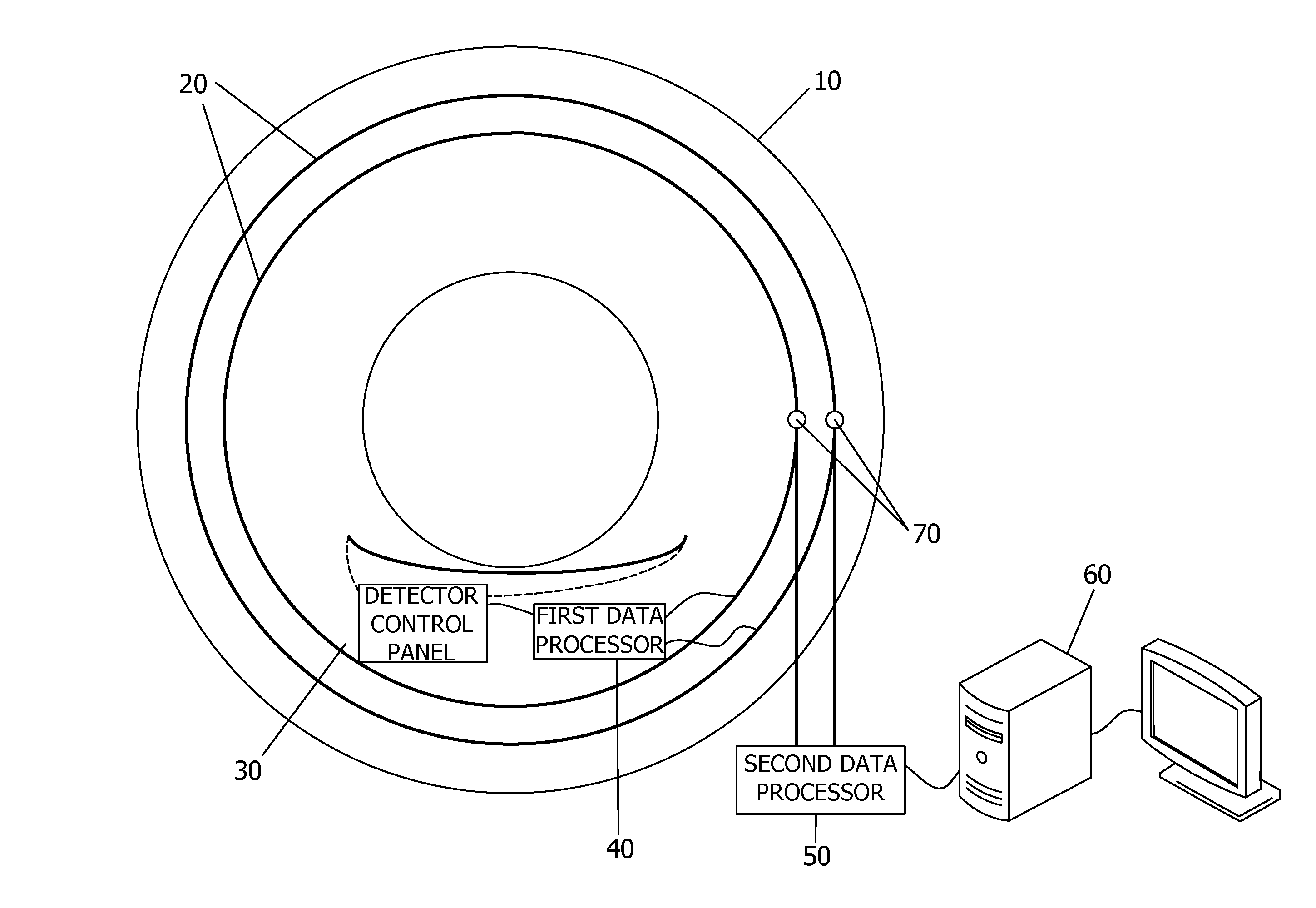
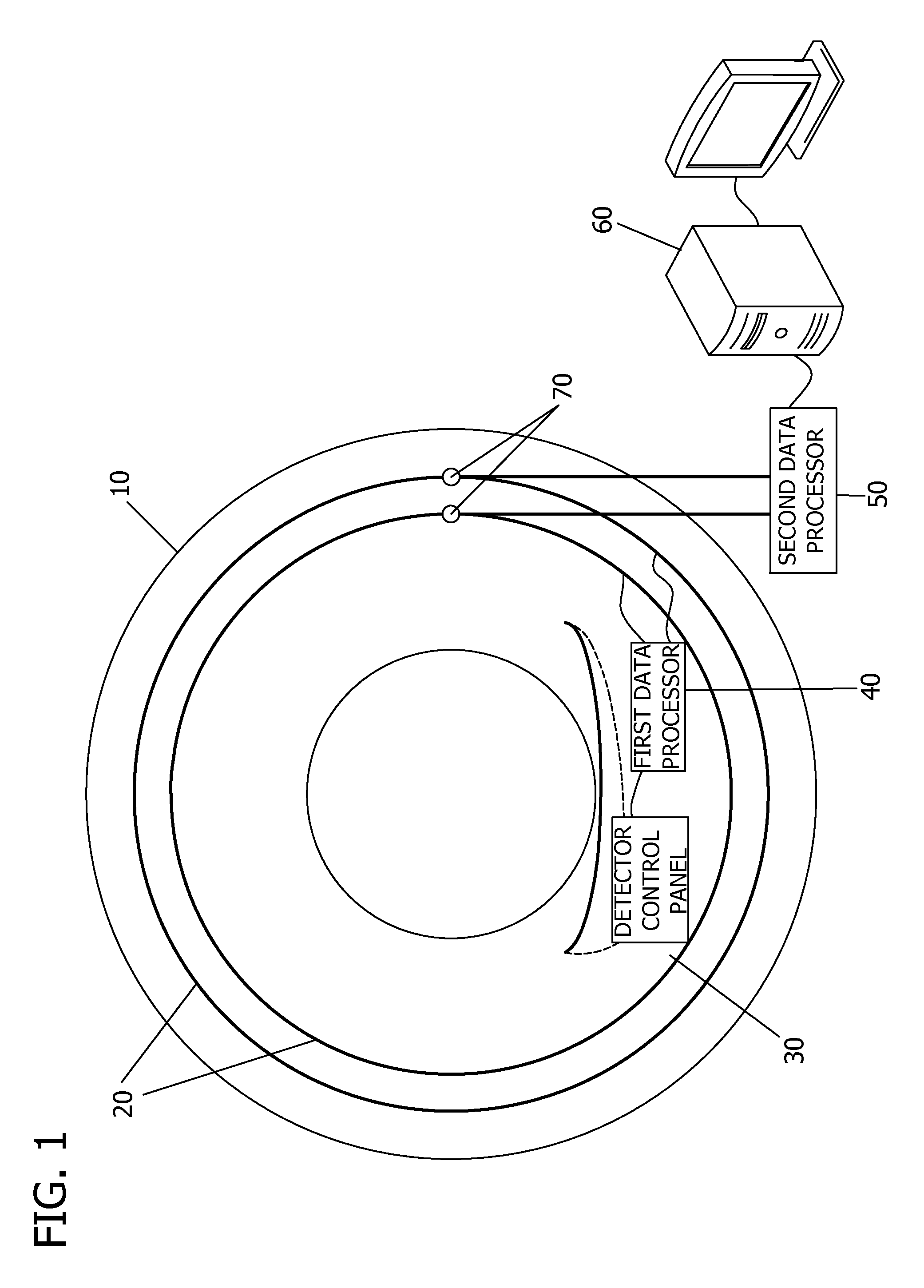
[0016]FIG. 1 is a structural representation of the CT scanner apparatus of the present invention, comprising a scanner gantry 10, a power ring 20, a detector control panel 30 for collecting scan data signal from the detector, a first data processor 40, a second data processor 50 and a controller 60; wherein, the scanner gantry 10 comprises a rotary part and a stationary part, the power ring 20, detector control panel 30 and first data processor 40 are mounted in the rotary part; the second data processor 50 is mounted in the stationary part of the scanner gantry 10. The detector control panel 30 collects the scan data signal and transmits the collected scan data signal by a data line to the first data processor 40. Data is transmitted between the detector control panel 30 and the first data processor 40 with tr...


PUM


Abstract

A Computerized Tomography (CT) scanner apparatus includes a scanner gantry, a detector, a detector control panel configured to control the detector, and a power ring. The scanner gantry includes a rotary part and a stationary part, wherein the detector, the detector control panel, and the power ring are mounted in the rotary part. The detector control panel is configured to transmit a scan data signal collected from the detector from the rotary part of the scanner gantry to the stationary part via a power line on the power ring.

Description

CROSS REFERENCE TO RELATED APPLICATIONS[0001]This application claims the benefit of Chinese Patent Application No. 200810176298.6 filed Nov. 21, 2008, which is hereby incorporated by reference in its entirety.BACKGROUND OF THE INVENTION[0002]The embodiments described herein relate to medical device technology, in particular to a Computerized Tomography (CT) scanner apparatus.[0003]The CT scanner apparatus comprises a scanner gantry, an X-ray generator and a detector mounted in the scanner gantry. The scan data collected by the detector, after being processed, must be transmitted from the rotary part of the scanner gantry to the stationary part of the scanner gantry to be further data processed or be displayed on a display. In a CT scanner apparatus, data transmission between the rotary part and the stationary part of the scanner gantry is a technical problem for all CT scanner apparatus to solve. The prior art is to add a slip ring and set a contact point thereon to implement data t...

Claims


Application Information

Patent Timeline
Patent Type & Authority Patents(United States)
IPC IPC(8): H05G1/64H05G1/02
CPCA61B6/56
Inventor MENG, DAZHUANG
Owner GE MEDICAL SYST GLOBAL TECH CO LLC
Why Eureka
Try Eureka