Vehicle front structure

a front structure and vehicle technology, applied in the direction of bumpers, roofs, vehicular safety arrangments, etc., can solve the problems of increased assembly labor, increased number of parts, increased cost of parts to be controlled, etc., to achieve the desired absorbing performance easily, facilitate assembly, and facilitate configuration

Active Publication Date: 2012-06-12
SUZUKI MOTOR CORP
View PDF15 Cites 13 Cited by
  • Summary
  • Abstract
  • Description
  • Claims
  • Application Information

AI Technical Summary

Benefits of technology

[0006]According to the above-described conventional structure, since the square tubular shock absorbing part separate from the bumper and the apron side member has been fixedly attached to the front end portion of the apron side member, the number of parts has been increased, so that the cost of parts to be controlled has increased. Also, the assembly labor has been increased, and much time and labor is required for assembly work.
[0007]The present invention has been made in view of the above circumstances, and accordingly, an object thereof is to provide a vehicle front structure in which the number of parts can be decreased to reduce the cost of parts to be controlled, the labor for assembly can be reduced, and assembly work can be simplified.

Problems solved by technology

According to the above-described conventional structure, since the square tubular shock absorbing part separate from the bumper and the apron side member has been fixedly attached to the front end portion of the apron side member, the number of parts has been increased, so that the cost of parts to be controlled has increased.
Also, the assembly labor has been increased, and much time and labor is required for assembly work.

Method used


Image

  • Vehicle front structure
  • Vehicle front structure
  • Vehicle front structure

Examples


Embodiment Construction

[0032]A best mode for carrying out the present invention will now be described with reference to the accompanying drawings.

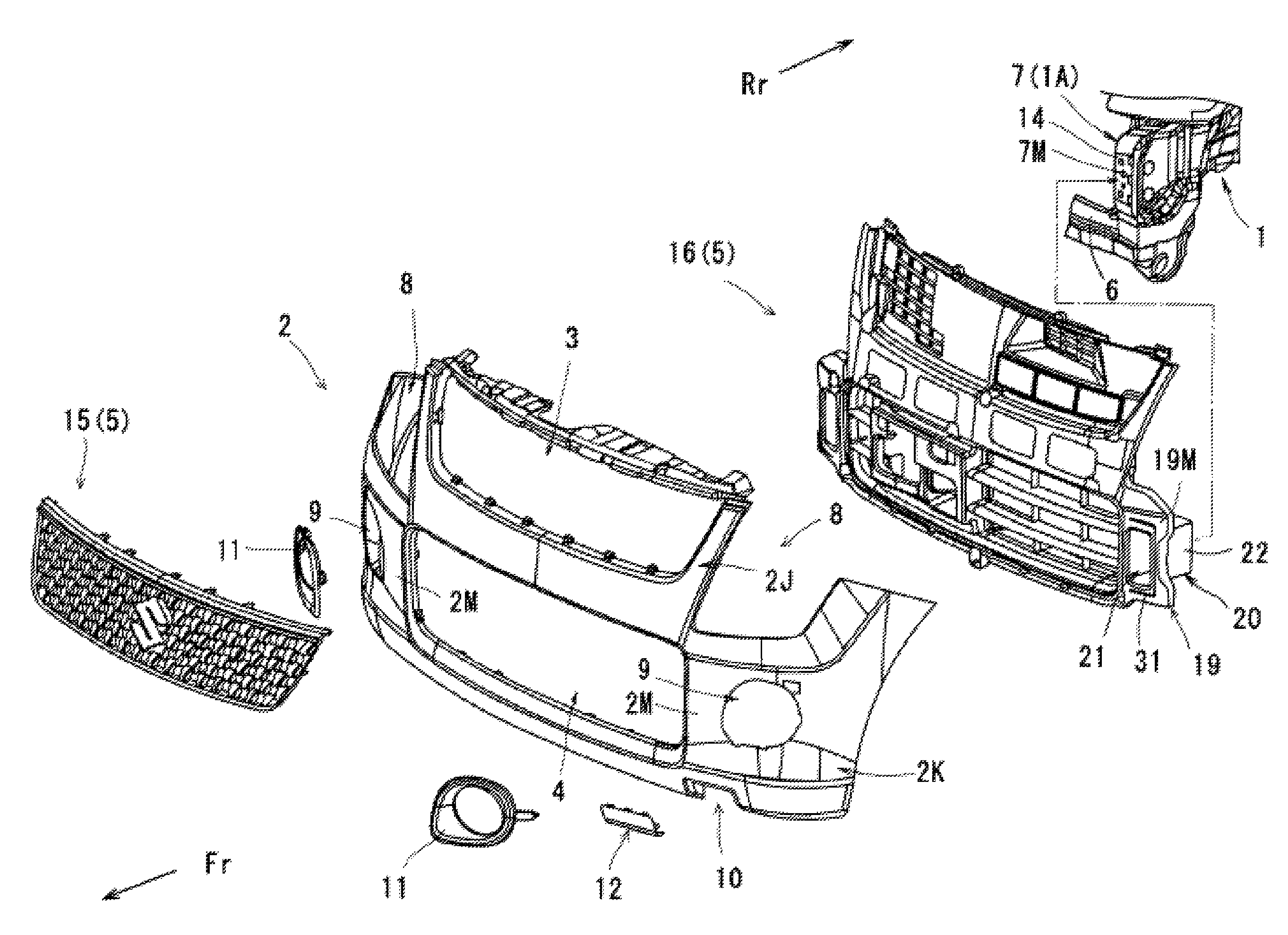
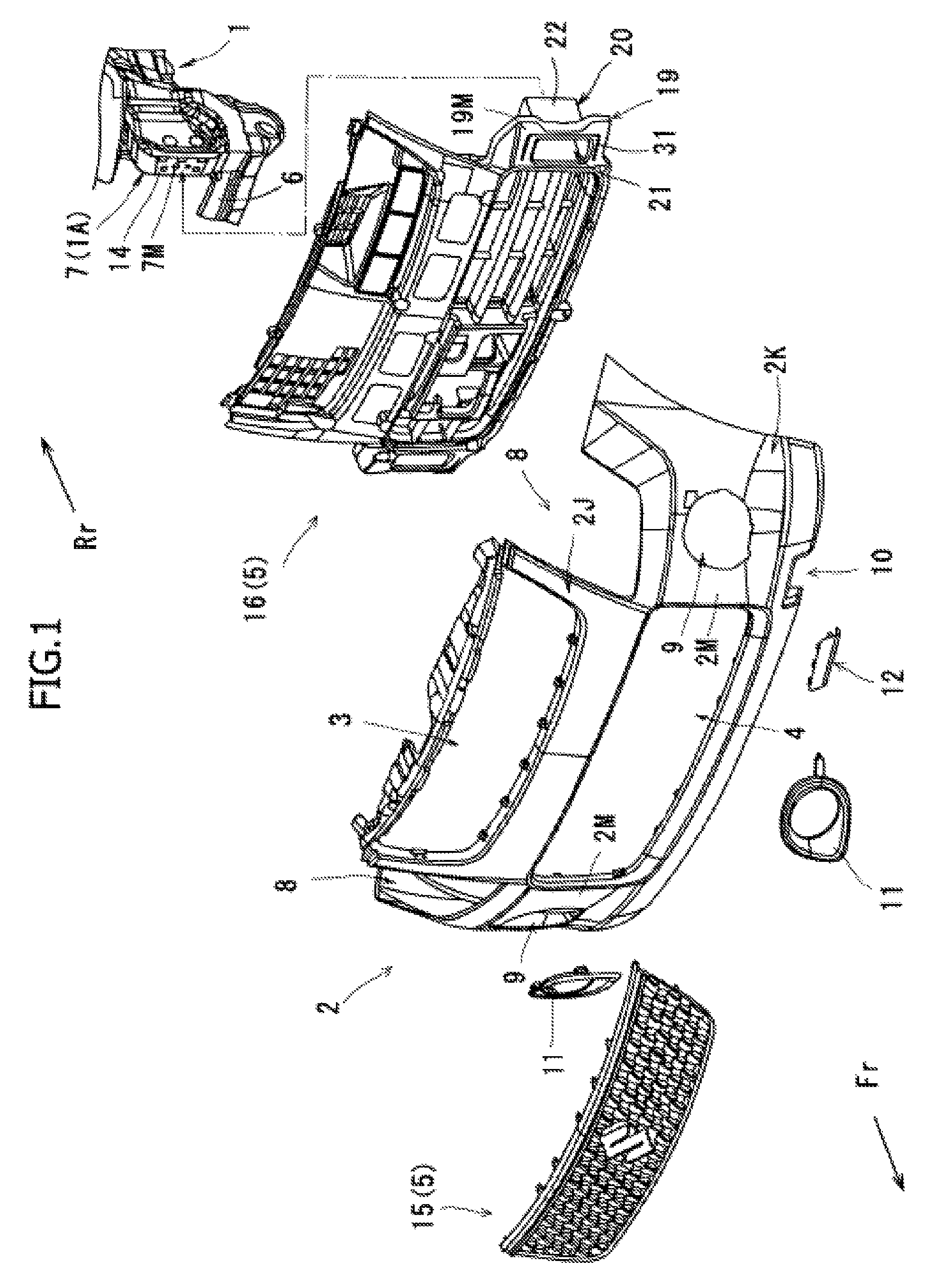
[0033]FIG. 1 is an exploded perspective view of a vehicle front. This vehicle front structure has a pair of right and left apron side members 1, each having a closed section structure, provided along the vehicle longitudinal direction, a bumper 2 located on the vehicle front side Fr of front end portions 1A of the apron side members 1, and a grille 5 attached to a pair of upper and lower air intake openings 3 and 4 of the bumper 2.

Structure of Apron Side Member 1

[0034]The apron side member 1 is formed in a rectangular shape having a longitudinally long cross section, and receives a shock load to suppress the deformation of vehicle body when a shock load is applied from the vehicle front side Fr. The front end portion 1A of the apron side member is configured as a plane perpendicular to the vehicle longitudinal direction by a gusset 7 of a rectangular shape havin...


PUM


Abstract

A vehicle front structure has a pair of right and left apron side members 1 each extending in the vehicle longitudinal direction and having a closed cross section structure, a bumper 2 located on the vehicle front side Fr of the front end portion of the apron side member 1, and a grille 5 attached to air intake openings 3, 4 in the bumper 2. In this vehicle front structure, shock absorbing parts 20 formed integrally with the grille 5 are disposed between the bumper 2 and the front end portions of the apron side members 1.

Description

CROSS-REFERENCE TO RELATED APPLICATIONS[0001]This application claims the benefit of priority from Japanese Patent Application No. 2009-081563, filed Mar. 30, 2009.BACKGROUND OF THE INVENTION[0002]1. Field of the Invention[0003]The present invention relates to a vehicle front structure, having a pair of right and left apron side members each having a closed sectional structure, which extend along the vehicle longitudinal direction, a bumper located on the vehicle front side of the front end portions of the apron side members, and a grille attached to an air intake opening of the bumper.[0004]2. Description of the Related Art[0005]An apron side member is a member having a strength, which constitutes the skeleton of a motor vehicle. When the motor vehicle is involved in a collision, if the strength of the collision object is low, the apron side member is less liable to deform and has difficulty in absorbing the shock load. Therefore, as disclosed in JP 2000-53017 A, a square tubular sh...

Claims


Application Information

Patent Timeline
Patent Type & Authority Patents(United States)
IPC IPC(8): B60R19/26B60R19/52
CPCB60R19/48B60R19/52B62D25/084B60R2019/486B60R2019/505B60R2019/525
Inventor OHNO, SHINJISUMINO, TAKUSHIGEMASU, HIRONORIMASUDA, IDEMITSUMIYAZAKI, AKITO
Owner SUZUKI MOTOR CORP
Why Eureka
Try Eureka