
System and method for spine stabilization using resilient inserts

Active Publication Date: 2012-06-12
ZIMMER BIOMET SPINE INC
View PDF172 Cites 15 Cited by
  • Summary
  • Abstract
  • Description
  • Claims
  • Application Information

AI Technical Summary

Benefits of technology

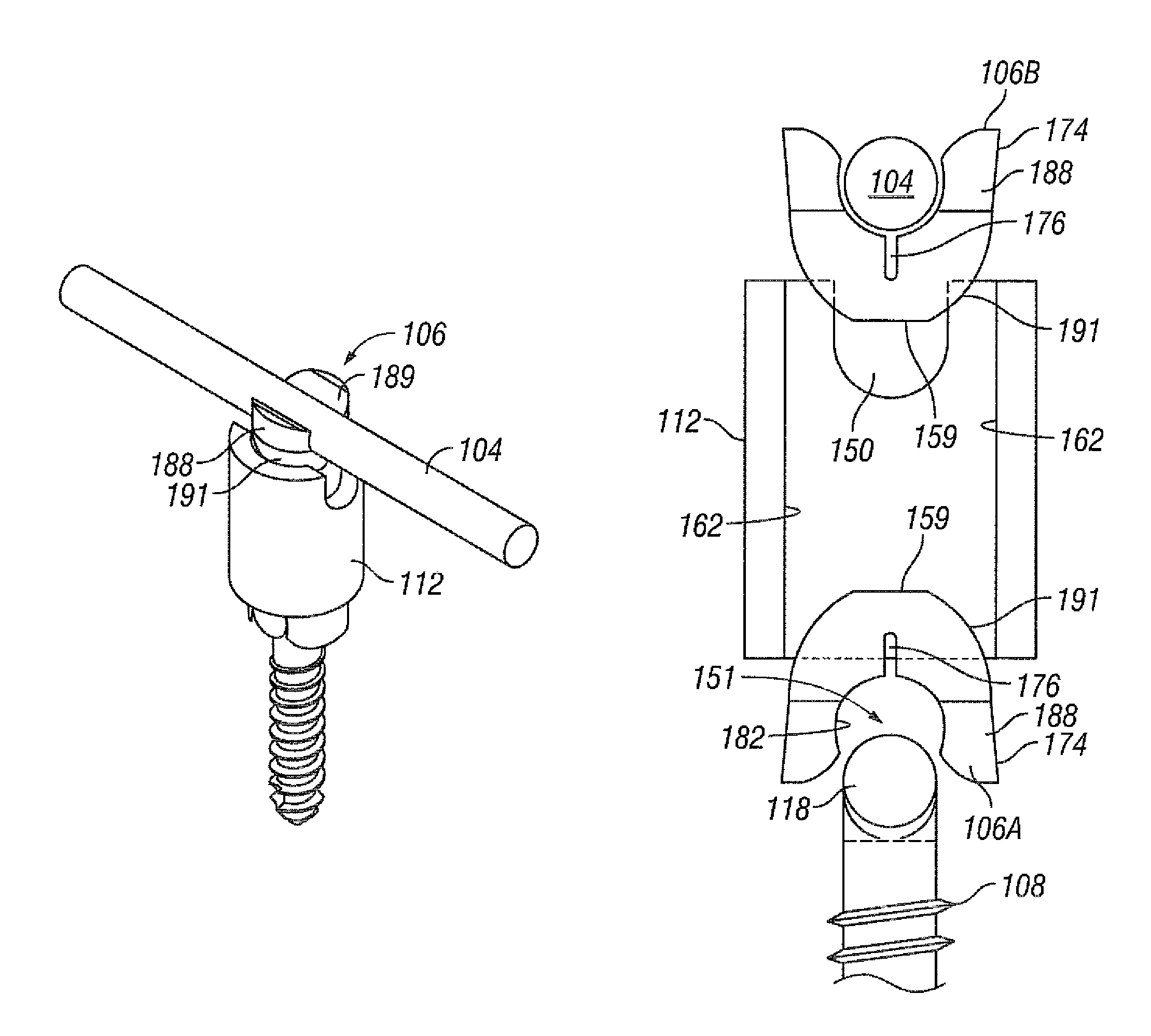
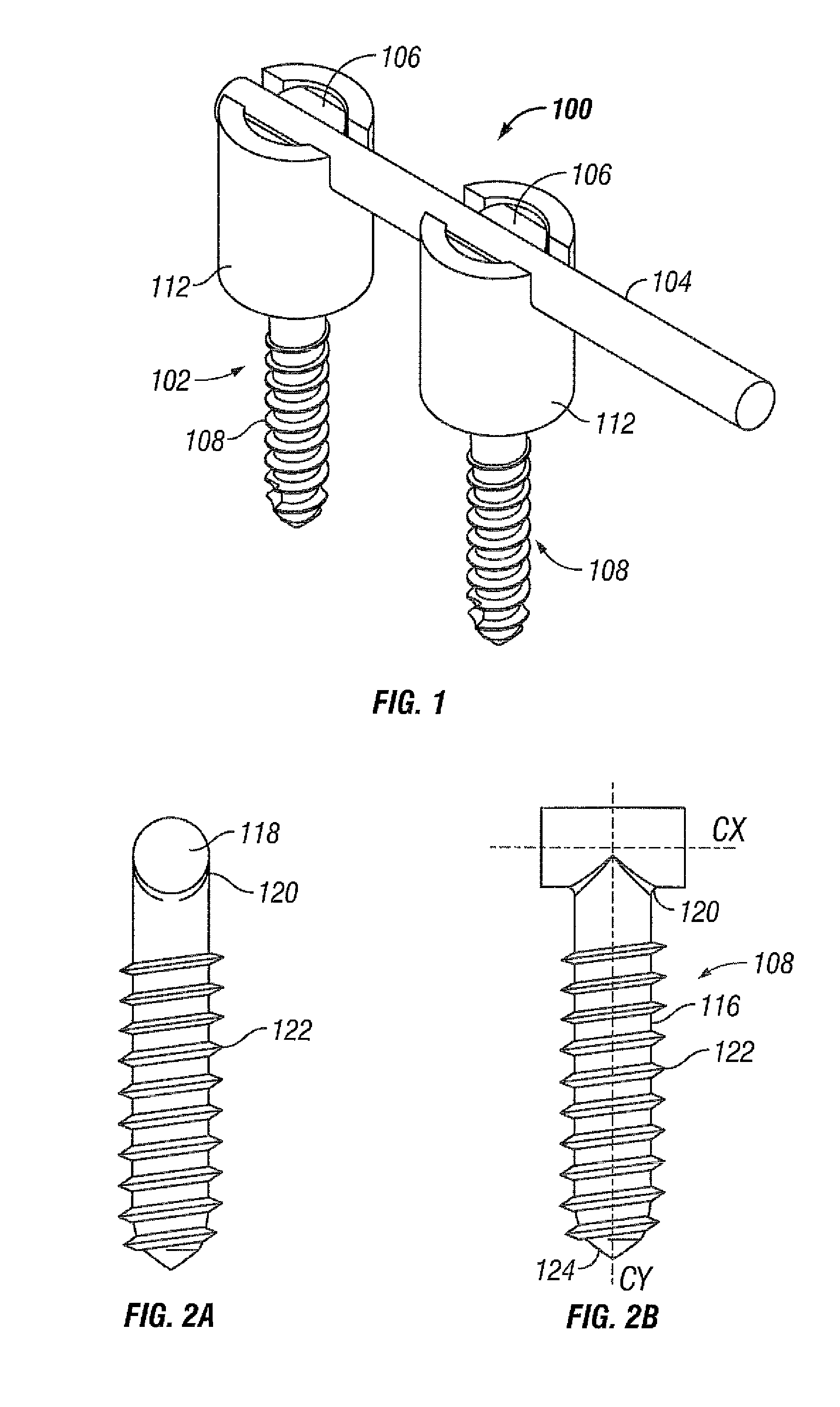
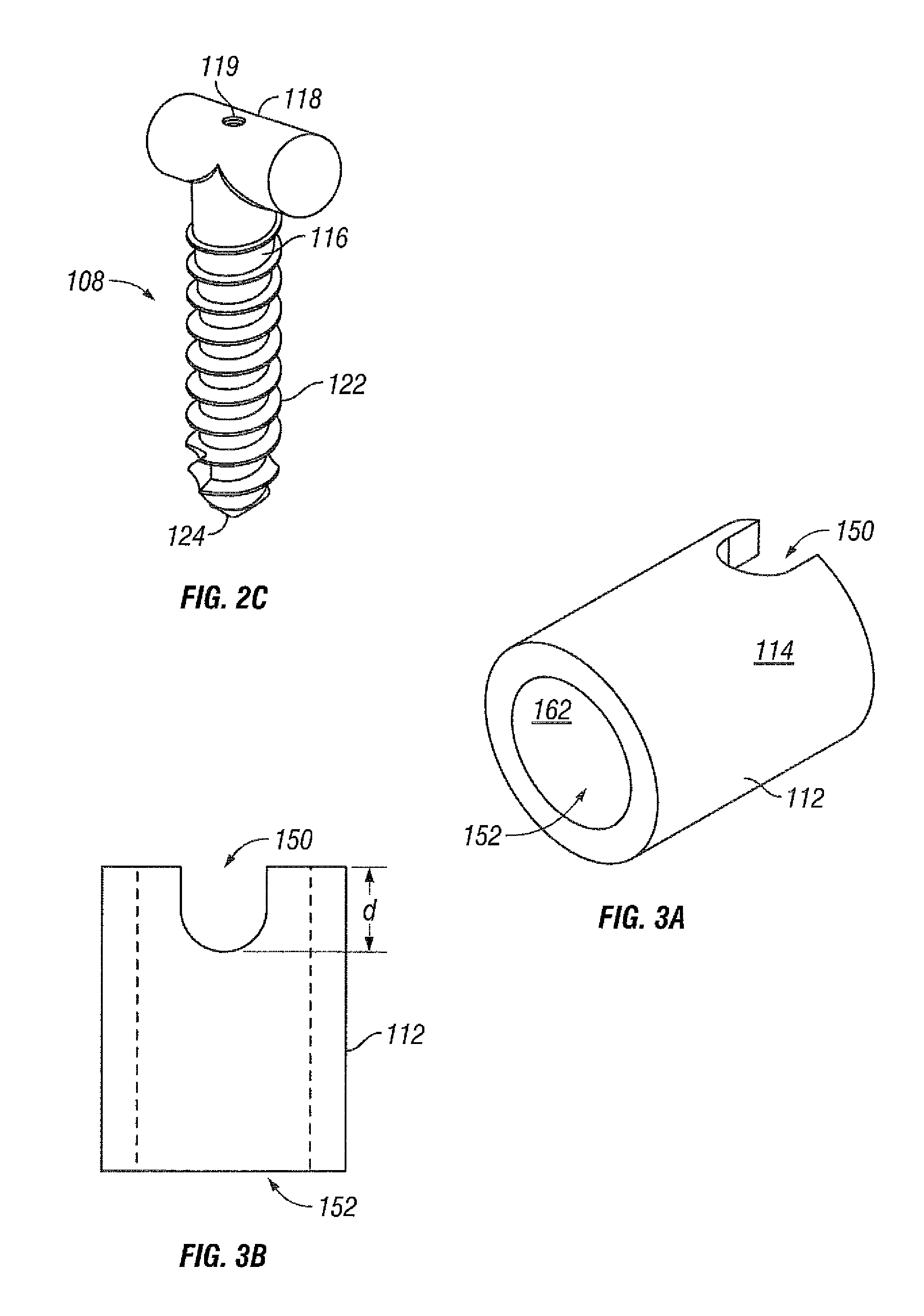
[0007]A spinal stabilization system may be used to achieve rigid pedicle fixation while minimizing the amount of damage to surrounding tissue. In some embodiments, a spinal stabilization system may be used to provide stability to two or more vertebrae. A spinal stabilization system may include a rod, two or more bone fastener assemblies, and / or a resilient insert. The bone fastener assembly may include a bone fastener and a cylindrical body. A first portion of the bone fastener may couple to a portion of the spine during use. A first portion of a cylindrical body may couple to a second portion of the bone fastener. A second portion of the cylindrical body may couple to a rod during use. In some embodiments, an orientation of the bone fastener may be independent of the orientation of the cylindrical body for a bone fastener assembly. After the bone fastener is placed in a vertebral body, the cylindrical body coupled to the bone fastener may be positioned so that the rod can be positioned in the cylindrical body and in at least one other cylindrical body that is coupled to another vertebral body by a bone fastener.

Problems solved by technology

Degeneration may destabilize bone and affect surrounding structures.
For example, destabilization of a spine may result in alteration of a natural spacing between adjacent vertebrae.
Pressure applied to the nerves may cause pain and / or nerve damage.
Minimally invasive procedures and systems may reduce recovery time as well as trauma to the soft tissue surrounding a stabilization site.

Method used


Image

  • System and method for spine stabilization using resilient inserts
  • System and method for spine stabilization using resilient inserts
  • System and method for spine stabilization using resilient inserts

Examples


Embodiment Construction

[0023]The invention and the various features and advantageous details thereof are explained more fully with reference to the non-limiting embodiments that are illustrated in the accompanying drawings and detailed in the following description. Descriptions of well known starting materials, processing techniques, components and equipment are omitted so as not to unnecessarily obscure the disclosure in detail. Skilled artisans should understand, however, that the detailed description and the specific examples, while disclosing preferred embodiments, are given by way of illustration only and not by way of limitation. Various substitutions, modifications, additions or rearrangements within the scope of the underlying inventive concept(s) will become apparent to those skilled in the art after reading this disclosure.

[0024]As used herein, the terms “comprises,”“comprising,”“includes,”“including,”“has,”“having” or any other variation thereof, are intended to cover a non-exclusive inclusion....


PUM

PropertyMeasurementUnit
Diameteraaaaaaaaaa
Widthaaaaaaaaaa
Resilienceaaaaaaaaaa

Abstract

An apparatus for anchoring a rod to a bone fastener in a spine stabilization system. A first resilient insert may have two deflectable arms and a first channel formed therein. A second resilient insert may have two deflectable arms and a second channel formed therein. A cylindrical body may have a passage, wherein the first resilient insert and the second resilient insert have a width greater than the inner diameter of the cylindrical body when the first resilient insert is in a neutral state. Advancement of the first resilient insert or the second resilient insert into the passage deflects the two deflectable arms inward, causing the width of the first or second channel to decrease, and inhibiting the first resilient insert or the second resilient insert from moving relative to the cylindrical body.

Description

BACKGROUND[0001]1. Field of the Disclosure[0002]The present disclosure generally relates to spinal stabilization systems. More particularly, embodiments of the disclosure relate to spinal stabilization systems that may have non-threaded portions for securing rods to bone fasteners.[0003]2. Description of Related Art[0004]Bone may be subject to degeneration caused by trauma, disease, and / or aging. Degeneration may destabilize bone and affect surrounding structures. For example, destabilization of a spine may result in alteration of a natural spacing between adjacent vertebrae. Alteration of a natural spacing between adjacent vertebrae may subject nerves that pass between vertebral bodies to pressure. Pressure applied to the nerves may cause pain and / or nerve damage. Maintaining the natural spacing between vertebrae may reduce pressure applied to nerves that pass between vertebral bodies. A spinal stabilization procedure may be used to maintain the natural spacing between vertebrae an...

Claims


Application Information

Patent Timeline
IPC IPC(8): A61B17/70
CPCA61B17/7032A61B17/7038Y10T29/49826
Inventor HUNT, WESLEYLE, H. KIMCHANG, ALEXQADIR, ANWAAR
Owner ZIMMER BIOMET SPINE INC
Learn More