
Adjustable probe

a probe and adjustment technology, applied in the field of endoscopic probes, can solve the problem that the desired direction of the exiting beam is not readily adjustable in such probes

Active Publication Date: 2014-10-16
LUMENIS LTD
View PDF9 Cites 0 Cited by
  • Summary
  • Abstract
  • Description
  • Claims
  • Application Information

AI Technical Summary

Benefits of technology

The present invention provides various forms of an endoscopic probe that have a tapered, bevelled, or chamfered distal end, which makes it easier to insert the probe, minimizes damage to surrounding tissue, and reduces damage to the endoscope wall. The probe may be straight or curved, with a gradual and slight curvature. The design of the probe is dictated by various factors, such as the dimensions of the channel and its curved parts, the length and dimension of the adjustable means, and the flexibility of the material. The adjustable means should be able to negotiate any curved section of the channel without getting jammed.

Problems solved by technology

Hitherto, the design of the latter type of probes has been dictated by the direction in which the exiting beam is required to travel respect to the elongate channel of the probe, and the desired direction of the exiting beam is not readily adjustable in such probes.
This is a first technical problem over a large range of probes known in the art.
A similar second technical problem to that described above arises in multichannel endoscopic probes which comprise an elongate working channel for a variety of non-laser surgical equipment for ablating, dissecting, excising and / or resecting hard or soft tissue, where it is desired to illuminate the treatment site from various directions.
This is a second technical problem which arises in providing a solution to the first technical problem.
Again, a similar second technical problem to that described above arises in multichannel endoscopic probes which comprise an elongate working channel for a variety of non-laser surgical equipment, where any such probe and any elongate channel in the probe are required to be narrow, but where it is desired to illuminate the treatment site from various directions.
It will be seen that the second technical problem arises in providing a solution to the first technical problem for narrow probes

Method used


Image

  • Adjustable probe
  • Adjustable probe
  • Adjustable probe

Examples


seventh embodiment

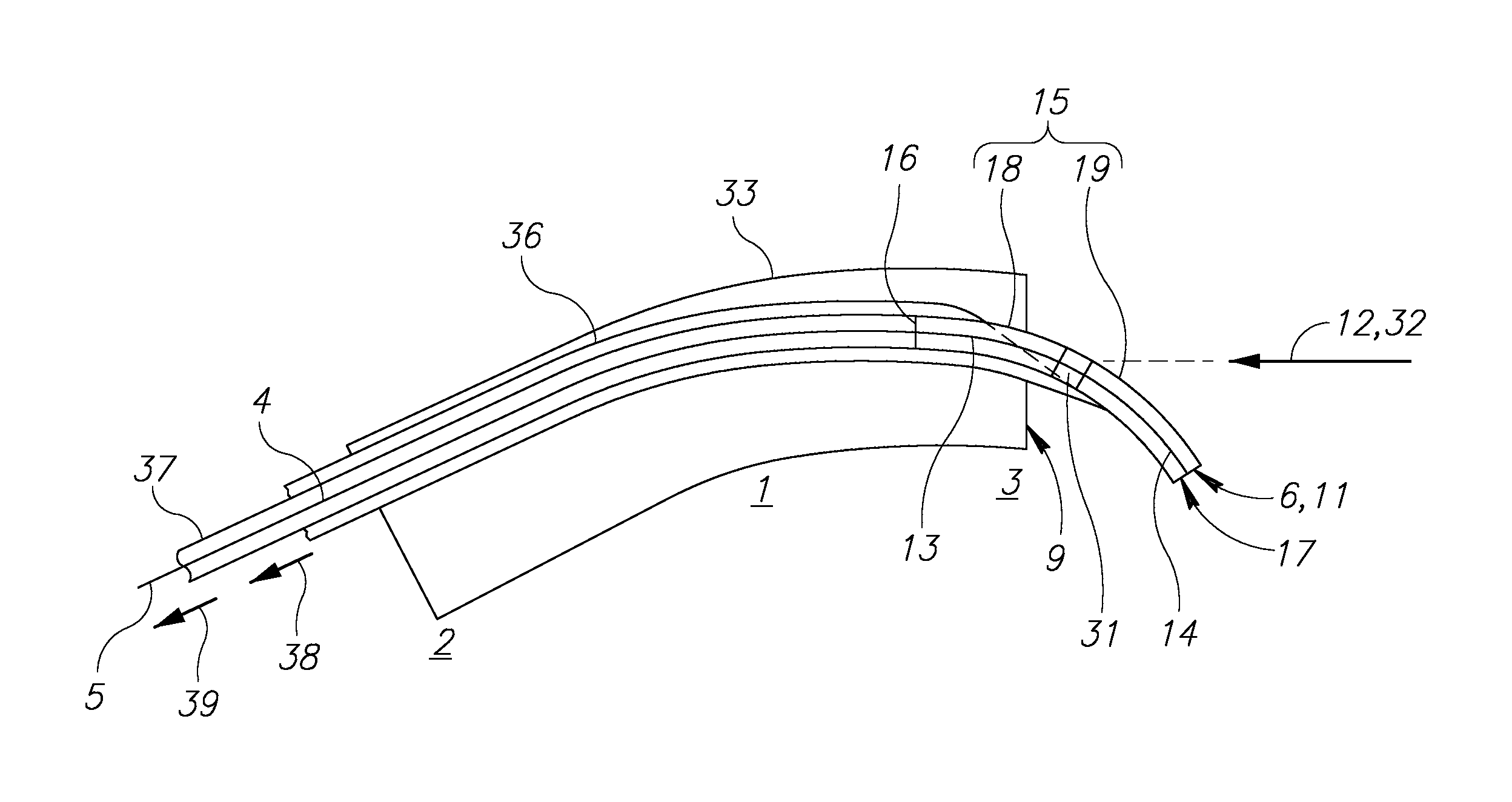
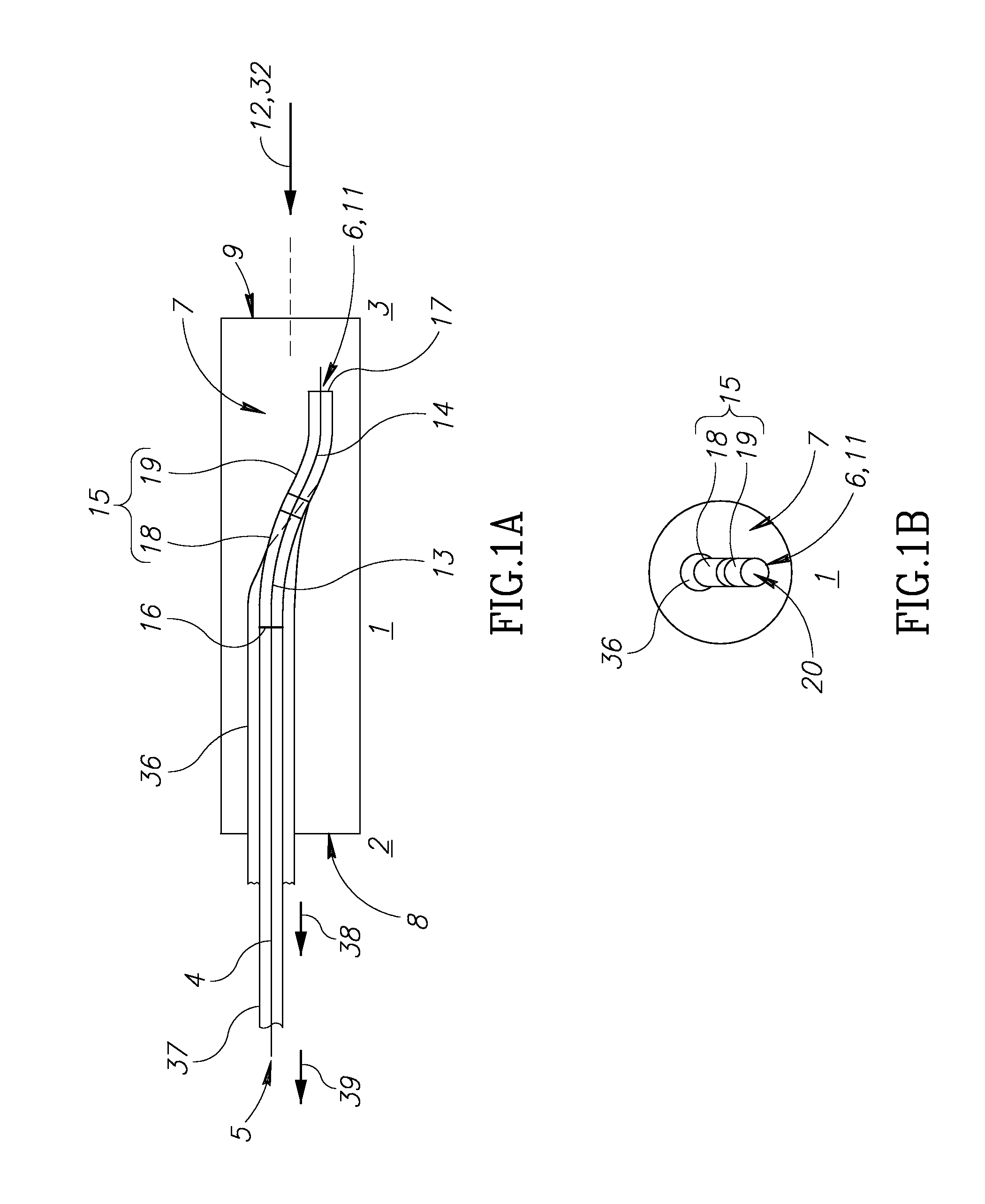
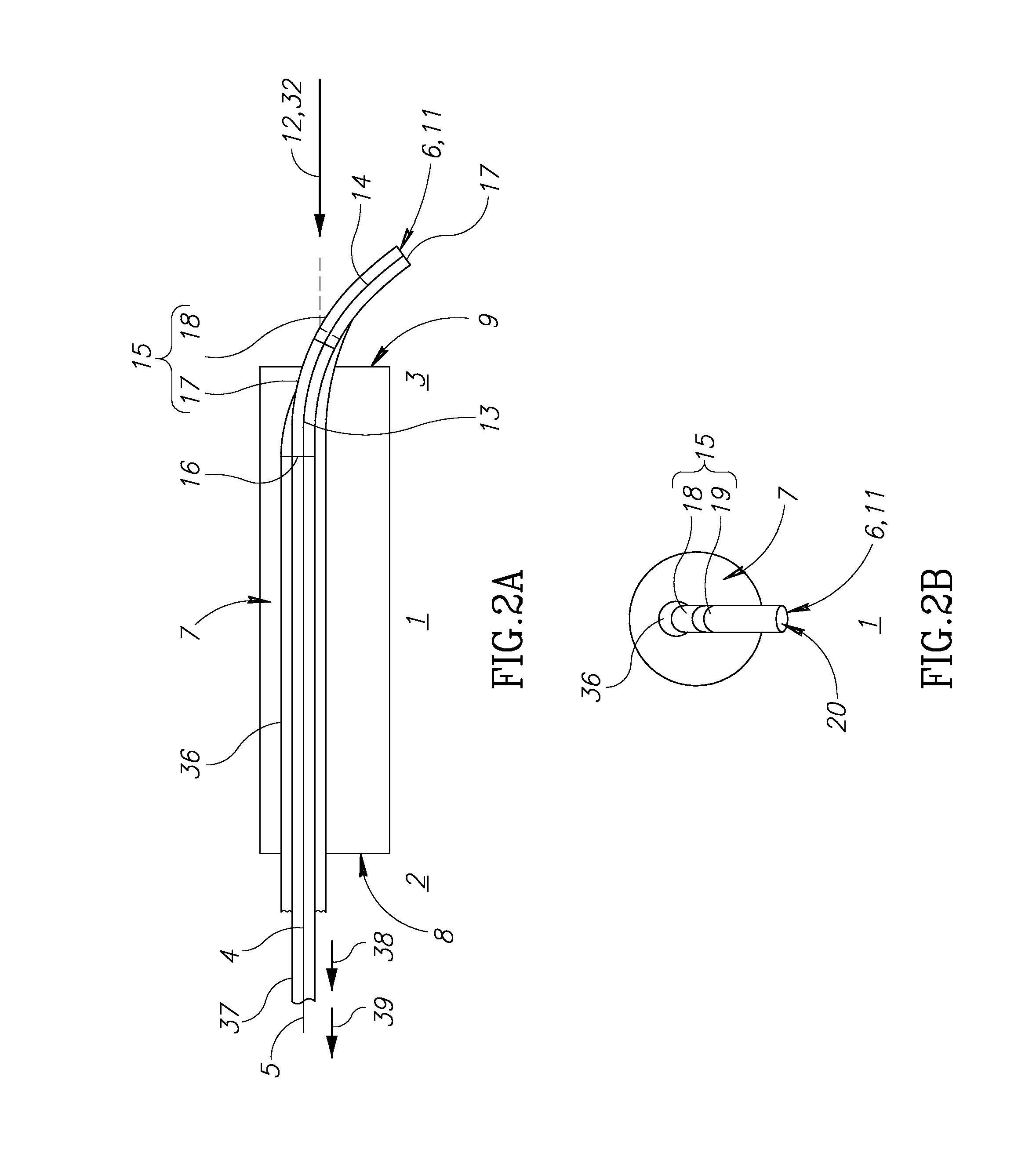
[0177]In the preferred form of the endoscopic probe (probe with narrow channel), the first and second adjacent curved portions of the fibre are separate, but optically connected, integers.

[0178]In this embodiment of this form of the endoscopic probe, one of the first and second adjacent sections of the sheath houses a part of the other section of the sheath to form one or more sliding bearing therebetween.

[0179]The first and second sections of the sheath are mutually rotatable about a common central axis at the sliding bearing or bearings. It may be convenient for the first and second portions of the fibre to have adjacent planar end surfaces, which are orthogonal to the longitudinal axis of the fibre at the location of the end surfaces.

[0180]The first and second adjacent curved portions within the curved sheath may be separated by a plastic transparent index matching material which creates optical coupling, and reduces Fresnel reflection at the interfaces, between the first and sec...

ninth embodiment

[0199]In the preferred form (probe with narrow channel), the adjustable means comprises a rigid, self-supporting curved full sheath, comprising first and second adjacent mutually rotatable curved sections. Either or both of the first and second sections of the sheath comprises a hollow light guide with a conduit with internally reflective surfaces.

[0200]One of the first and second adjacent sections of the sheath houses a part of the other section of the sheath to form a circumferential sliding bearing therebetween where one section of the sheath houses a part of the other, and the first and second sections of the sheath are mutually rotatable about a common central axis at the sliding bearing.

[0201]The distal section may house the proximal or vice versa. Where the relevant end of the housed section seats fully in the housing section at this bearing, it will also form an axial sliding bearing therebetween.

[0202]As described hereinbefore for the second, preferred embodiment of this fo...


PUM


Abstract

An optical fibre endoscopic probe used to deliver radiation, in particular laser radiation, during a surgical procedure. The configuration of components of the endoscopic probe in use is adjustable so as to direct the radiation which exits the fibre as desired. The present invention also relates to a device used to direct the exiting beam of radiation in such an endoscopic probe, which may in particular be used in a narrow probe channel, for example for prostate laser surgery, and to a method of surgical treatment using the endoscopic probe.

Description

FIELD OF THE INVENTION[0001]The present invention relates to an endoscopic probe used to deliver radiation, in particular laser radiation during a surgical procedure. The configuration of components of the endoscopic probe in use is adjustable so as to direct the radiation which exits the fibre as desired. The present invention also relates to a device used to direct the exiting beam of radiation in such an endoscopic probe, and to a method of surgical treatment using the endoscopic probe.[0002]The term ‘curved’, when used herein with reference to curved portions of a waveguide (as defined below), and the curved sections of the adjustable means, means that the respective integer has a major curvature, which is other than the minor curvature of the (often) tubular surfaces of the integer.[0003]The term ‘longitudinal axis’, when used herein with reference to any point along an endoscopic probe of the present invention, the elongate channel of the probe, the optical fibre or the adjust...

Claims


Application Information

Patent Timeline
IPC IPC(8): A61B18/20A61B1/07
CPCA61B18/201A61B2018/2035A61B1/07A61B18/22A61B2018/00547A61B1/00096A61B1/00165A61B1/00174A61B18/20A61B2018/2238A61B2018/2244A61B2018/2288
Inventor KHACHATUROV, ARKADY
Owner LUMENIS LTD
Learn More