Wind turbine generator
a wind turbine generator and wind turbine technology, applied in the direction of electric generator control, machine/engine, gearing, etc., can solve the problems of increasing the weight affecting the operation of the installation site, so as to facilitate the replacement process of the drive train, reduce the weight of the support structure, and compact structure.
- Summary
- Abstract
- Description
- Claims
- Application Information
AI Technical Summary
Benefits of technology
Problems solved by technology
Method used
Image
Examples
first embodiment
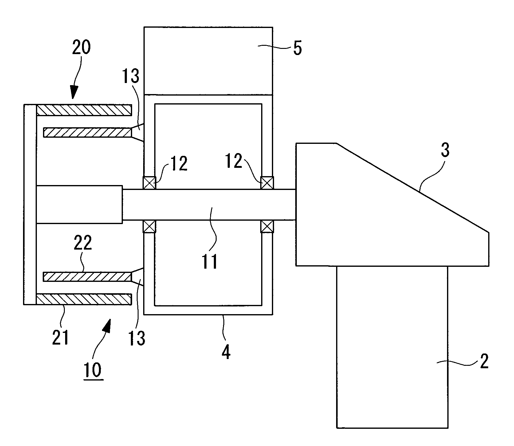
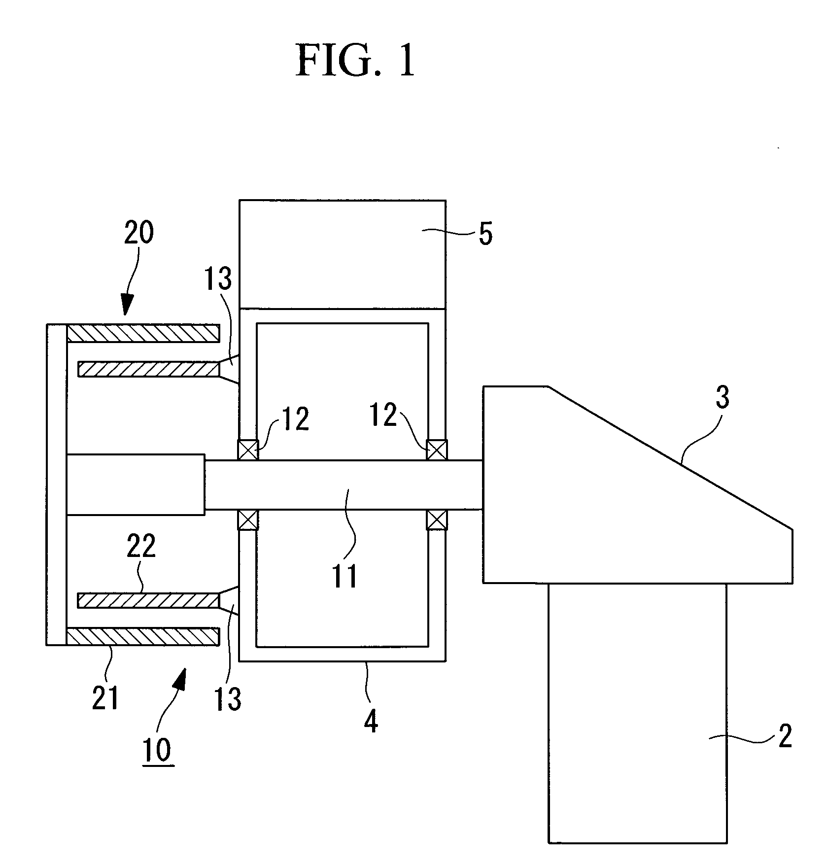
[0064]FIG. 1 is an enlarged cross-sectional view of showing a relevant part of an example of an internal configuration of the rotor head 4 disposed in front of the nacelle 3 and a drive train 10 disposed in front of the rotor head 4 in a state where a rotor-head cover (not shown) is removed. In the embodiment to be described below, the drive train 10 is configured to transmit the rotation of the rotor head 4 directly to a generator 20 without intervention of a speed-increasing gearbox.
[0065]In FIG. 1, the rotor head 4 having the wind-turbine rotor blade 5 is supported by a main shaft 11, which protrudes forward from the nacelle 3, via bearings 12. In other words, when the wind-turbine rotor blade 5 receive wind, the rotor head 4 rotates together with the wind-turbine rotor blade 5 about the main shaft 11 securely supported by the nacelle 3.
[0066]A cylindrical stator 21 that constitutes the generator 20 is provided at an end of the main shaft 11 securely supported by the nacelle 3. A...
second embodiment
[0073]Next, a second embodiment of the wind turbine generator according to the present invention will be described with reference to FIG. 4. Components similar to those in the above embodiment will be given the same reference numerals, and detailed descriptions thereof will be omitted.
[0074]A drive train 10A in this embodiment is equipped with a speed-increasing gearbox 30 between the rotor head 4 and the generator 20 for increasing the speed of rotation of the rotor head 4 and transmitting it to the generator 20. In this case, the speed-increasing gearbox 30 is a single-stage planetary speed-increasing gearbox, and reference numeral 31 in the drawing denotes a sun gear and 32 denotes planet gears.
[0075]In the aforementioned speed-increasing gearbox 30, the sun gear 31, which is rotatably supported by the end of the main shaft 11 via bearings 12, is meshed with the plurality of planet gears 32, which are supported by the front face of the rotor head 4 via a rigid coupling 14, and th...
third embodiment
[0081]Next, a third embodiment of the wind turbine generator according to the present invention will be described with reference to FIG. 5. Components similar to those in the above embodiments will be given the same reference numerals, and detailed descriptions thereof will be omitted.
[0082]A drive train 10B in this embodiment is equipped with a speed-increasing gearbox 30A between the rotor head 4 and the generator 20 for increasing the speed of rotation of the rotor head 4 and transmitting it to the generator 20. In this case, the speed-increasing gearbox 30A is a single-stage star-type speed-increasing gearbox, and reference numeral 31A in the drawing denotes a sun gear and 32A denotes planet gears. The planet gears 32A in the star-type speed-increasing gearbox 30A are rotatable by being supported by the main shaft 11 at the fixed side, and are meshed with a gear section 33a at the outer peripheral side, which is formed on an inner peripheral surface of a casing 33A that rotates ...
PUM
 Abstract
Description
Claims
Application Information
 - R&D
- Intellectual Property
- Life Sciences
- Materials
- Tech Scout
- Unparalleled Data Quality
- Higher Quality Content
- 60% Fewer Hallucinations
Browse by: Latest US Patents, China's latest patents, Technical Efficacy Thesaurus, Application Domain, Technology Topic, Popular Technical Reports.
© 2025 PatSnap. All rights reserved.Legal|Privacy policy|Modern Slavery Act Transparency Statement|Sitemap|About US| Contact US: help@patsnap.com


