Tape device having a tape cleaning structure

a cleaning structure and tape drive technology, applied in the field of tape drives, can solve the problems of inability to easily obtain a sufficient cleaning effect, inability to produce advanced cleaning effects, limitations, and conventional cleaning structures to achieve advanced cleaning effects, eliminate read errors, and high clean state

Active Publication Date: 2012-06-12
FUJIFILM CORP
View PDF20 Cites 2 Cited by
  • Summary
  • Abstract
  • Description
  • Claims
  • Application Information

AI Technical Summary

Benefits of technology

[0014]Moreover, in the cleaning structure of the Patent Document 5, a suction hole is opened at the peripheral surface of the tape guide, and the blade is placed in a center portion in the widthwise direction of the suction hole. Therefore, much time and labor are needed for the processing and assembling of the tape guide and the blade. Since the dust is scraped off by the thin blade placed at the center in the widthwise direction of the suction hole, the blade is easily worn out, and much time and labor are needed for the maintenance. Furthermore, the conventional cleaning structures, which can remove the dust on the tape surface, are not able to remove the dust adhering to the tape edges (that is, tape side edges) that are the end portions of tape side surfaces. Therefore, it is sometimes the case where the dust that has adhered to the tape edges adheres to the tape surface, and this consequently causes the dropout of the servo signals in writing the servo signals or read error in reading the servo signals.
[0015]An object of the present invention is to provide a tape device capable of maintaining a tape in a highly clean state by reliably removing not only dust on the tape surface but also dust adhering to the tape edges. That is, the object is to provide a tape device excellent in reliability capable of reliably reading and writing servo signals and information signals by eliminating the dropout of a servo signal in writing the servo signals in a servo writer and read errors in reading the servo signals in the tape drive.
[0041]In the cleaning structure for removing dust having the above construction, at first, the dust adhering to the tape surface is removed by the vacuum pressure effected on the suction port in the first dust removal portion. In addition, dust remaining on the tape surface is separated from the tape surface by bringing the tape surface in contact with the opening edge of the suction port on the downstream side in the tape running direction and removed by the vacuum pressure effected on the suction port. Further, in the second dust removal portion, the dust adhering to at least one tape edge of the tape can be removed by bringing the tape edge in contact with the guiding wall. That is, the dust adhering to the tape surface is removed in the first dust removal portion, and the dust adhering to the tape edge can be removed in the second dust removal portion. Therefore, the tape can be put into a highly clean state by removing the dust from the surface and the edge of the tape that has passed through the cleaning structure in the tape running path.
[0042]As a result, read and write of the servo signals and the information signals can reliably be performed without causing the dropout of the servo signal in writing the servo signals in the tape device of, for example, a servo writer and by eliminating read errors in reading the servo signals in, for example, a tape drive. Therefore, a tape device excellent in reliability can be provided.
[0043]Moreover, the cleaning structure for removing dust as described above has a comparatively compact structure in which the suction port and the guiding wall are provided for the guiding member. Therefore, the cleaning structure can be installed in a small space, and a necessary number of the cleaning structures can be placed in necessary places. It is noted that the amount of dust removed in the second dust removal portion is very little in comparison with the amount of dust removed in the first dust removal portion. Therefore, by wipingly removing the dust adhering to the second dust removal portion after a lapse of every prescribed time or taking a similar measure, the state of the guiding member can be restored into an appropriate state.

Problems solved by technology

Moreover, if even a minute amount of dust is adhering to the tape surface in reading and writing information signals on a magnetic tape cartridge, a servo signal read error occurs, failing in accurately tracing the data track and consequently leading to impaired reliability of the tape drive.
However, conventional cleaning structures cannot produce an advanced cleaning effect and have limitations.
For example, the cleaning structures of the Patent Documents 1, 2, which use a cleaning tape, cannot easily obtain a sufficient cleaning effect.
In addition, the tape material, or, for example, the constituent nonwoven fiber of the cleaning tape separates and adheres to the tape surface, possibly causing serious read and write errors.
Moreover, since a space occupied by a set of cleaning structures is large, it is difficult to provide a plurality of cleaning structures for the tape device and to improve the dust removing effect.
In the cleaning structure of the Patent Document 3, in which the dust and the like on the tape surface are scraped off by the opening edge of the groove formed on the peripheral surface of the tape guide, the dust scraped off cannot be prevented from accumulating at the opening edge of the groove, and much time and labor are needed for removing the dust scraped off.
Furthermore, it is also concerned that the dust accumulated at the opening edge might re-adhere to the tape surface.
Therefore, it is concerned that the dust scraped off by the blade might not be sucked into the suction hole but accumulated at the leading end of the blade.

Method used


Image

  • Tape device having a tape cleaning structure
  • Tape device having a tape cleaning structure
  • Tape device having a tape cleaning structure

Examples


Embodiment Construction

[0054]Before the description of the present invention proceeds, it is to be noted that like parts are designated by like reference numerals throughout the accompanying drawings.

[0055]Hereinbelow, embodiments of the invention will be described in detail with reference to the drawings.

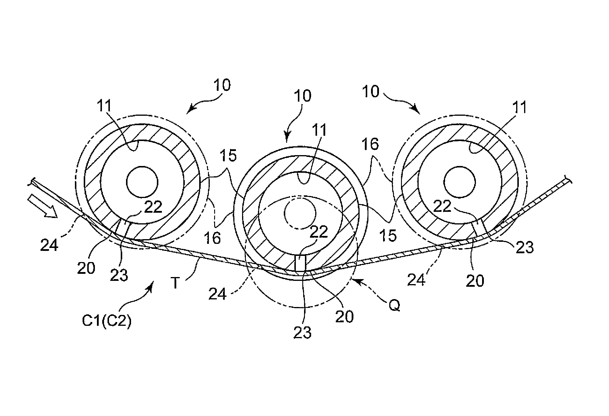
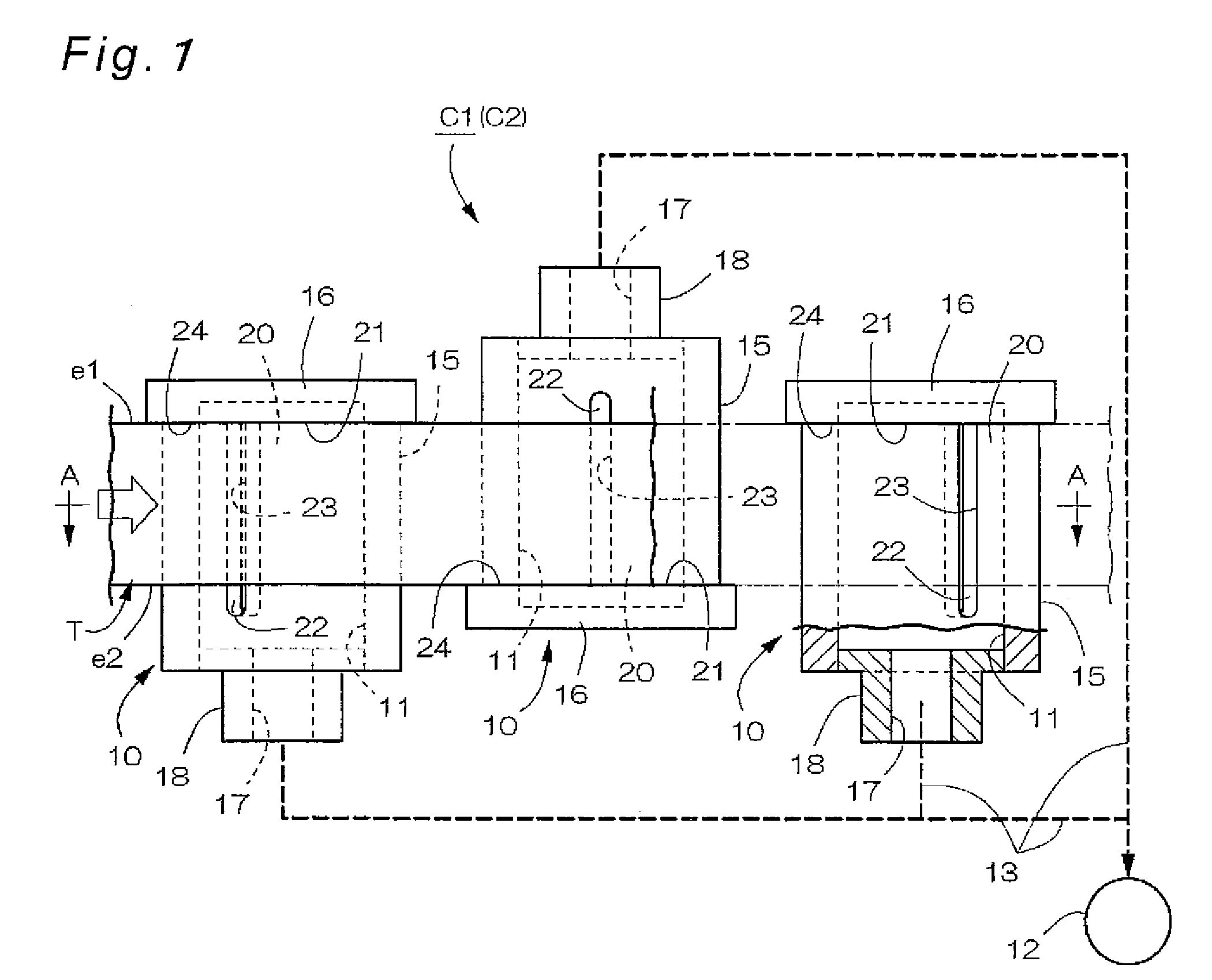
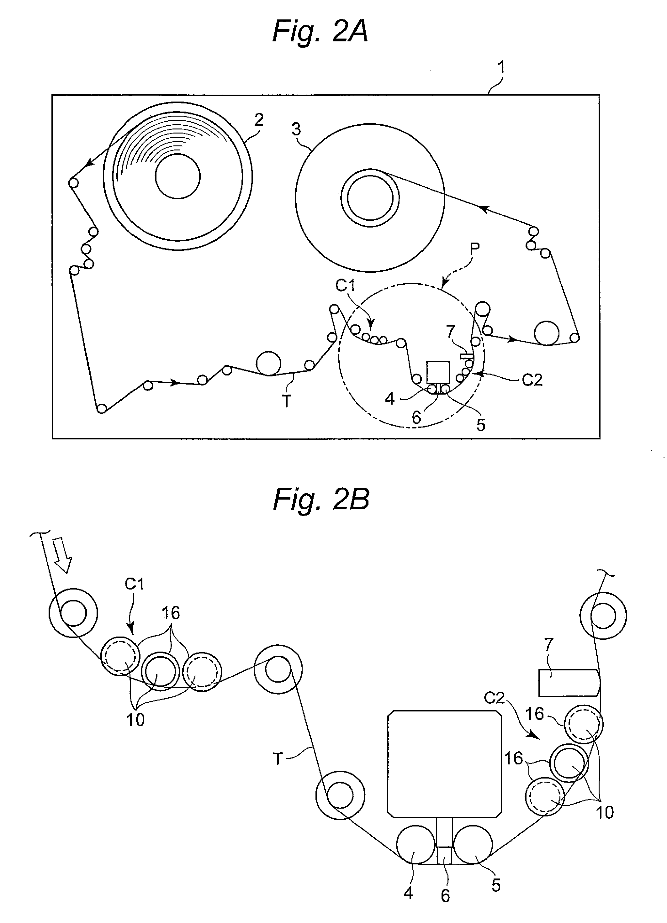
[0056]FIGS. 1, 2A, 2B, 3A and 3B are views showing an embodiment in which the tape device of the present invention is applied to a servo writer. As shown in FIGS. 2A and 2B, the servo writer has an unwinding reel 2 and a takeup reel 3 on the right-hand and left-hand sides of the front surface of its machine body 1. The servo writer is constructed so that a magnetic tape (sometimes referred to simply as a “tape”) T unwound from the unwinding reel 2 can be fed to the takeup reel 3 while being guided during running by a plurality of groups of tape guides. That is, the tape T runs along the plurality of tape guides arranged on the running path of the tape T with the unwinding reel 2 served as a commencing en...


PUM

PropertyMeasurementUnit
widthaaaaaaaaaa
recording wavelengthaaaaaaaaaa
vacuum pressureaaaaaaaaaa

Abstract

A cleaning structure for removing dust is constituted of a guiding member having a sliding surface for guiding run of a tape, and a vacuum pressure supply source for making a vacuum pressure effect on a suction space provided inside the guiding member and so on. At the sliding surface of the guiding member, a suction port for making the suction space communicate with an external space is formed, and the opening edge of the suction port on the downstream side in the tape running direction is served as a first dust removal portion for removing dust on the tape surface. The guiding member has a guiding wall having a contact surface which guides at least one tape edge of a tape, and the contact surface is served as a second dust removal portion for removing dust adhering to the tape edge.

Description

BACKGROUND OF THE INVENTION[0001]1. Field of the Invention[0002]The present invention relates to a tape device having a structure for removing dust and the like adhering to a tape surface. The tape device of the present invention means a servo writer for writing servo signals, a tape drive for reading and writing information signals.[0003]2. Description of Related Art[0004]Conventionally, a tape device of, for example, a servo writer has removed dust and the like adhering to a tape surface by providing a cleaning structure on the upstream side of a writing head in the tape running direction in order to avoid the dropout of a servo signal in writing the servo signals. As a cleaning structure of this kind, the type that removes dust and the like on the tape surface by wiping off with a cleaning tape (e.g., Patent Documents 1 and 2) is well known. Moreover, a cleaning structure in the other type of scraping off dust and the like on the tape surface by an edge portion of a groove formed...

Claims


Application Information

Patent Timeline
Patent Type & Authority Patents(United States)
IPC IPC(8): G11B23/50B08B5/04
CPCG11B15/60G11B23/502
Inventor HATA, YUKIHIROFUJITANI, SHIGEOSATO, JUNICHITAKAI, HISASHIKUSE, SADAMU
Owner FUJIFILM CORP
Why Eureka
Try Eureka