Optical sensor for detecting and localizing events

a technology of optical sensors and events, applied in the field of optical fences, can solve the problems of limited sensitivity and immunity to various noises, system optimization not fully optimized for use in applications, and prior art does not provide such desirable functionality

Inactive Publication Date: 2012-06-12
CELIGHT
View PDF9 Cites 22 Cited by
  • Summary
  • Abstract
  • Description
  • Claims
  • Application Information

AI Technical Summary

Problems solved by technology

In addition, assets can now be monitored where previously this was impractical due to their size, complexity, location or environment.
Most of the existing distributed sensors are based on Distributed Scattering Sensing (Raman or Brillion), which has a limited sensitivity and immunity to various noises.
While interferometer-based sensor systems have been developed with a number of refinements, such systems have not been fully optimized for use in applications that require simultaneous monitoring of different types of objects.
The prior art does not provide such desirable functionality.
As a result, received counter-propagating signals can potentially interfere constructively or destructively.
Although existing security application of distributed sensor systems are valuable in detecting events over large areas, they are not always sufficiently sensitive, capable of dynamic adjustment / control, convenient in implementation, properly camouflaged or economical for determining the location of events of different nature at different areas.
Operational pipelines are subject to complex, highly non-linear temporal and spatial processes that usually make it difficult to differentiate between faults and stochastic system behaviors.
This makes detecting failures / intrusions a challenging task, leading to integrating different types of data that is remotely captured from several sources, such as proposed fiber-optic system, as well as pressure transient signals and flow (velocity) information.

Method used


Image

  • Optical sensor for detecting and localizing events
  • Optical sensor for detecting and localizing events
  • Optical sensor for detecting and localizing events

Examples


Embodiment Construction

[0036]The present invention will now be described more fully hereinafter with reference to the accompanying drawings, in which the preferred embodiments of the invention are shown. This invention may, however, be embodied in many different forms and should not be construed as limited to the embodiments set forth herein; rather, these embodiments are provided so that this disclosure will be thorough and complete, and will fully convey the scope of the invention to those skilled in the art.

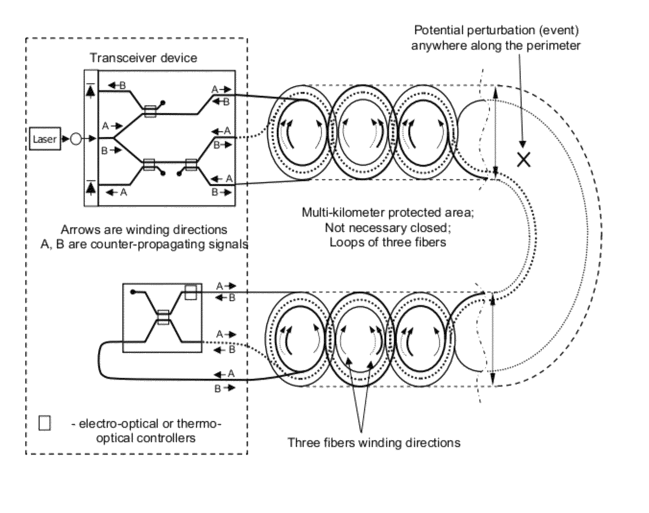
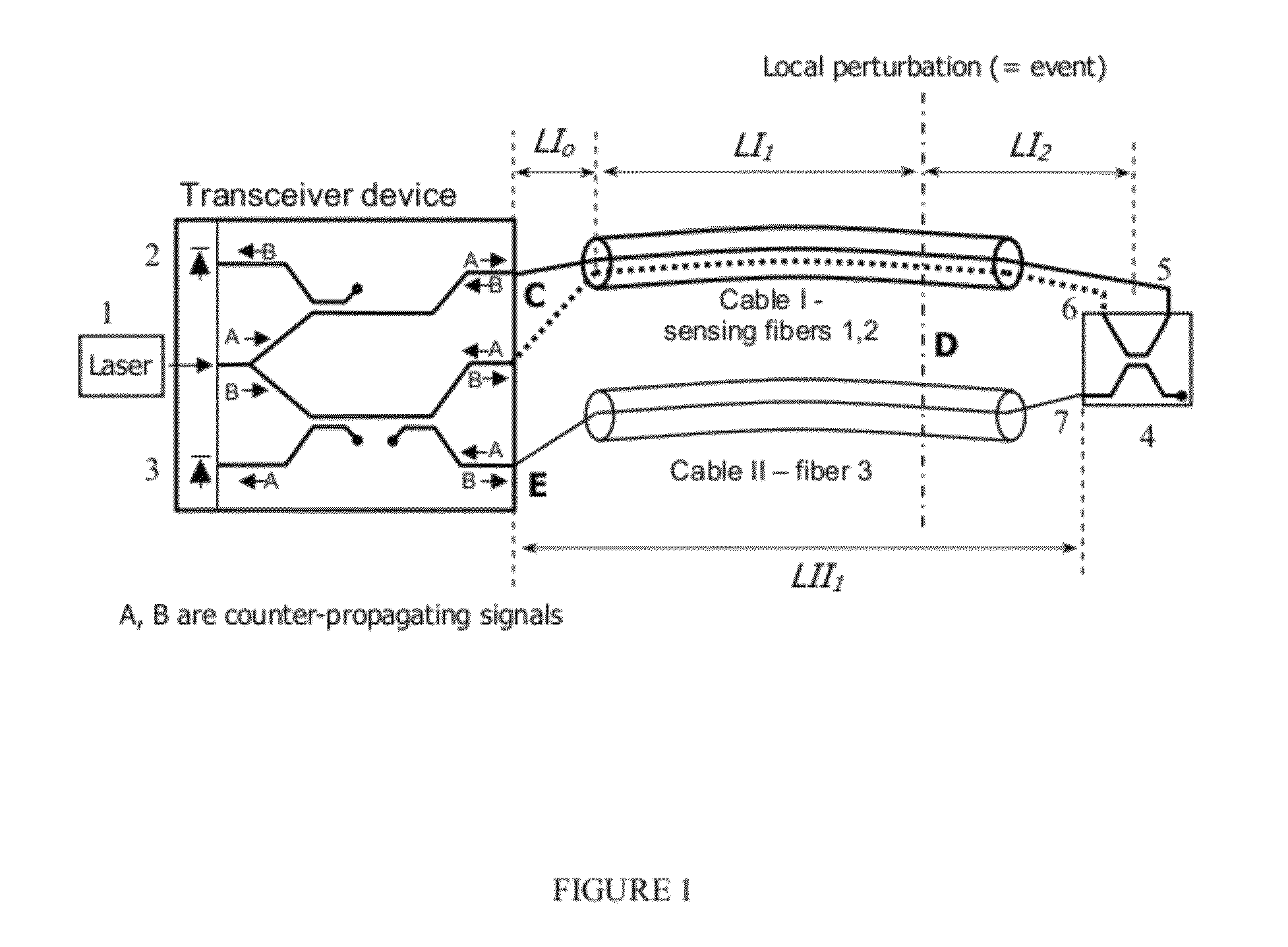
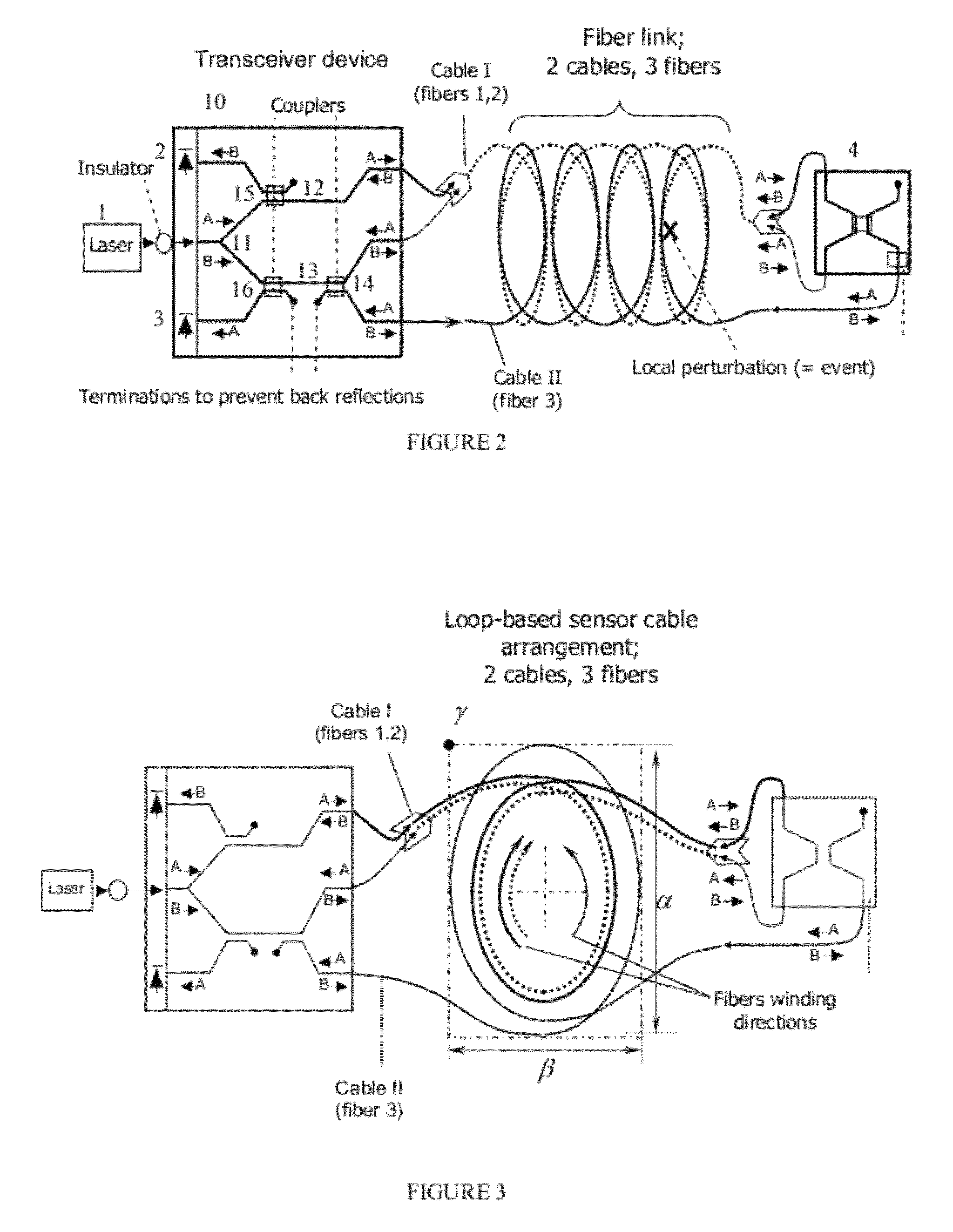
[0037]The system is designed for structure monitoring and disturbance detection and locating. The sensitivity to the potential perturbation can vary along the fiber cable, depending on the requirements within a particular area. Thus, the sensitivity of the system at particular area can be optimized in terms of local structural layout, depend on how often the perturbation occurs (event probability) or reflect the different types of event within different areas (different types of damage, intrusions, ...


PUM


Abstract

A system and method for a structure monitoring and locating a disturbance event is disclosed. The system includes a compact transceiver chip sending optical signals in three optical fibers that encompass the monitored structure appropriately. The system contains a sequence of loops, wherein the first and the second fiber forming the loop clockwise, while the third fiber is winded along the same loop counterclockwise. A set of two detectors registers the returning signals, and a time delay between those signals is calculated, which is indicative of the disturbance event location. The event location is determined with different sensitivity in different parts of the monitored structure depending on the density of fibers in these parts.

Description

CROSS-REFERENCE TO RELATED APPLICATIONS[0001]This application is a continuation-in-part of U.S. patent application Ser. No. 12 / 466,128 filed May 14, 2009 now U.S. Pat. No. 7,646,944.FIELD OF INVENTION[0002]The invention is related to systems that provide information for detecting and localizing events. In particular the invention relates to optical fences with a distributed fiber interferometer sensor to determine the location of a disturbance event along the object of interest and / or extensive perimeter area under observation.BACKGROUND OF THE INVENTION[0003]Fiber optic distributed sensing overcomes the inherent limitations of traditional technologies, such as motion detectors, cameras, thermocouples and strain gauges, enabling monitoring solutions with new advantages for the protection of people and critical assets, especially when monitoring in inaccessible or inhospitable environments.[0004]In a distributed sensor, the whole optical cable is the sensor itself. Typically, the fib...

Claims


Application Information

Patent Timeline
Patent Type & Authority Patents(United States)
IPC IPC(8): G02B6/00G01J1/04G08B13/00
CPCG01M5/0091G01M11/083G08B13/186G02B6/4246
Inventor KAPLAN, ARKADYSHPANTZER, ISAAC
Owner CELIGHT
Why Eureka
Try Eureka