

Corneal and epithelial remodelling
a corneal and epithelial technology, applied in the field of corneal and epithelial remodelling, can solve the problems of requiring an extensive period of time to reshape the cornea, carries the risk of both the procedure itself and post-surgical complications, and the manner in which such lenses operate, and in particular the physiology of the process of corneal reshaping, so as to achieve good vision
- Summary
- Abstract
- Description
- Claims
- Application Information
AI Technical Summary
Benefits of technology
Problems solved by technology
Method used
Image

Examples
example 1
Ray Tracing Method
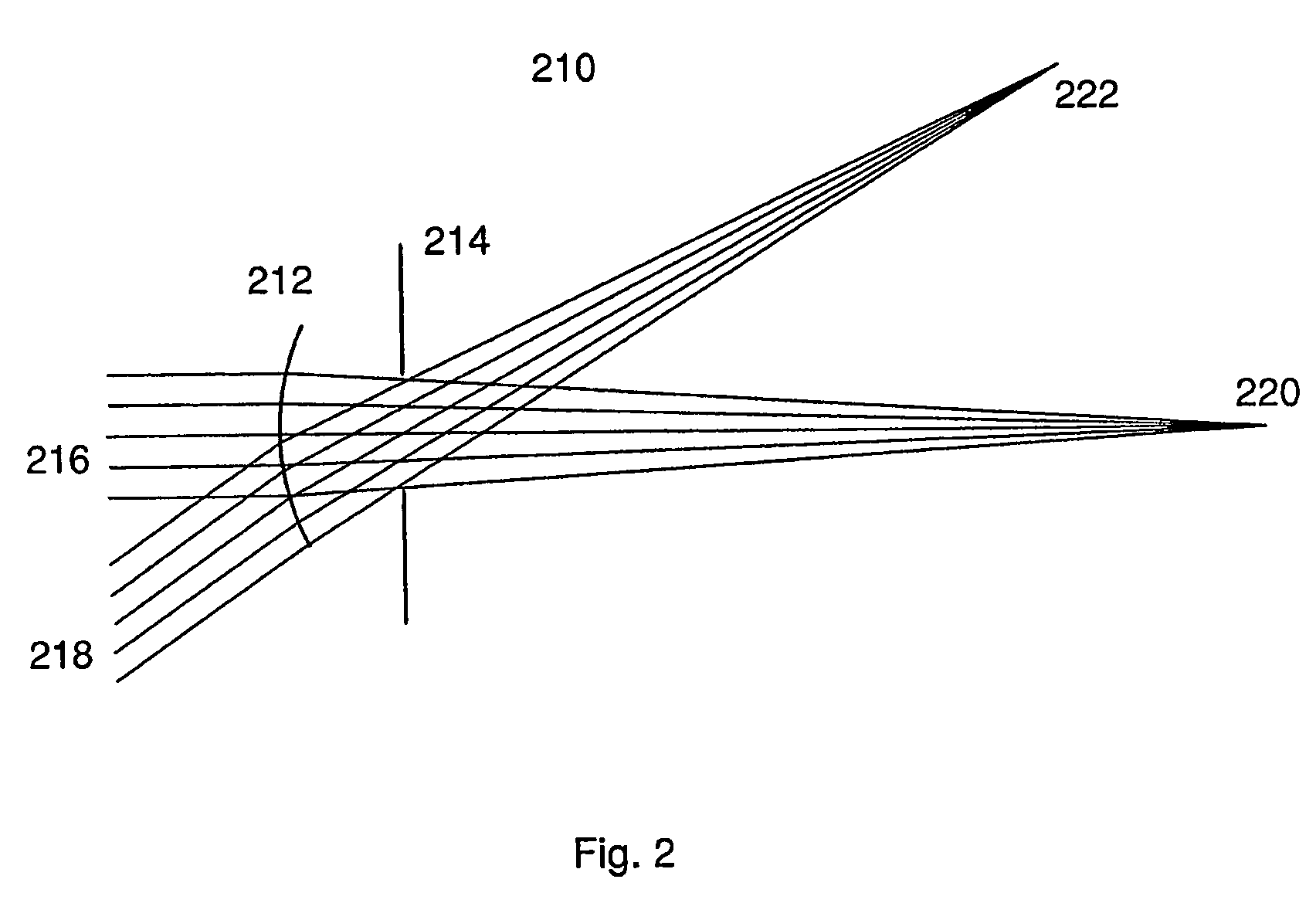
[0078]In FIG. 2, an optical model as described above is laid out in a commercially-available software (Zemax, Zemax Inc) for optical design. The surface 212 representing the cornea is for a patient whose corneal shape was measured to be equivalent to a conics section with central radius of 7.70 mm and shape factor of 0.80. By optimisation for minimum RMS distribution of the light rays' intersection with the image surface at both the central and peripheral field angles, the focal positions associated with the central 220 and peripheral field 222 angles were found. These, by computation, were found to be equivalent to a central corneal power of Fc=49.0 D and a peripheral corneal power at 350 of Fp=54.1 D.
[0079]For this example, suppose the patient's central and peripheral refractive state were found to be A=−6.00 D and B=−5.00 D. Further, supporting it was desired to provide an enhanced myopia therapy by introducing an additional amount of myopic defocus to the perip...
example 2
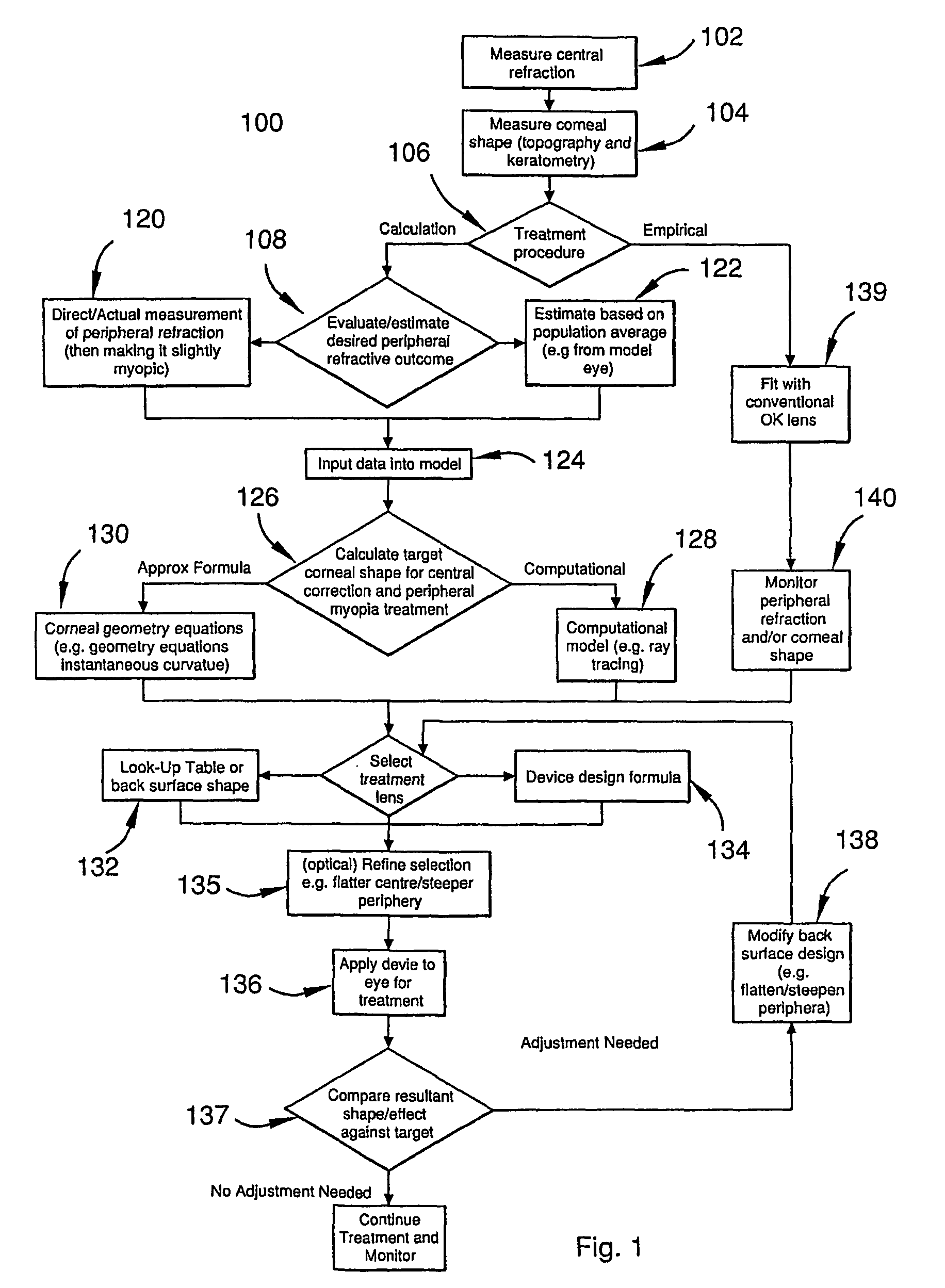
[0160]A myopic patient is to be treated by applying a device of the current invention. The procedure described in FIG. 1 was followed making use of the more precise computer-assisted ray-tracing method. The patient was measured for central distance refraction (with a result of −4.00 D) using clinical refraction techniques understood by ophthalmic practitioners. Then the patient was measured for corneal shape using a corneal topography system typically available in ophthalmic clinics (e.g. a videokeratograph). In this example, the corneal shape was summarised by the corneal topography output as having a central radius of R0=7.70 mm with a shape factor of p=0.80. Next the peripheral refraction of the patient was measured using standard refraction equipment and techniques but with the additional step of instructing the patient to gaze ‘side on’ to the refraction instrument. In this example, the peripheral refraction was measured at the field angle of 35° and found to be −3.00 D (i.e. t...
example 3
[0165]A patient was found to have −8.00 D of myopia (i.e. central refractive state). It was decided to treat her progression of myopia by orthokeratology using the device of this invention. In this example, the ophthalmic practitioner did not have access to a corneal topography system (e.g. videokeratograph) and peripheral refractive state measurement was not available for the particular patient. As a starting point for estimating the corneal shape, with the unavailability of a corneal topography, a keratometer was used to measure the central radius of curvature of the cornea. (A keratometer is a commonly available ophthalmic clinical instrument for measuring central corneal curvature. While in actuality, the keratometer measures an average radius around the central corneal region, this value is close enough to the central radius Ro of a cornea for the current purpose of arriving at an approximate shape for the cornea as a starting point.) The keratometer found a radius of 7.80 mm. ...
PUM
 Abstract
Description
Claims
Application Information