Motor rotor, having magnet holding projections

a technology of magnet holding and motor rotor, which is applied in the direction of magnetic circuits, electrical apparatus, dynamo-electric machines, etc., can solve the problems of decreasing the adhesive strength, the adhesive is subject to stress when the motor generates heat, and the adhesive strength decreases similarly. to achieve the effect of enhancing the reliability of the fixing of the segment magn

Inactive Publication Date: 2012-06-19
JTEKT CORP
View PDF7 Cites 11 Cited by
  • Summary
  • Abstract
  • Description
  • Claims
  • Application Information

AI Technical Summary

Benefits of technology

[0007]With the foregoing in view, an object of the invention is to provide a motor rotor capable of enhancing reliability of fixing of segment magnets to a rotor yoke, an electric power steering apparatus and a production process of the motor rotor.
[0009]According to this embodiment, each segment magnet is sandwiched in the width direction by the plurality of projections provided on the rotor yoke, thereby restricting each segment magnet from shifting in the width direction. In addition, the pair of end claws obtained by bifurcating the end of each projection into two prongs locks to the curved surface of the segment magnets, thereby preventing detachment of the segment magnets toward the outward direction of the rotor. As a result thereof, the reliability of fixing the segment magnets to the rotor yoke is enhanced, and the output torque of the motor is stabilized.
[0013]According to this embodiment, pieces of the segment magnets are prevented from flying off by the cylindrical cover even if a portion of the segment magnets are chipped.
[0015]Since the electric power steering apparatus as claimed in this embodiment is provided with a drive source in the form of a motor having a high degree of reliability of fixing of the segment magnets to the rotor yoke, both the output torque of the motor and steering feel are stable.

Problems solved by technology

However, since the coefficients of thermal expansion differ between the rotor yoke and the segment magnets, the adhesive is subjected to stress when the motor generates heat.
When there are frequent opportunities for the motor being used at a high load and reaching a high temperature, the adhesive undergoes thermal deterioration resulting in a decrease in adhesive strength thereof.
In addition, the adhesive strength of the adhesive similarly decreases in cases of being exposed to high temperatures and high-temperature environments for prolonged periods of time.
Consequently, in the case segment magnets are fixed to a rotor yoke with an adhesive alone as in the structure of the related art, there is the possibility of the segment magnets separating from the rotor yoke and the output torque of the motor becoming unstable.

Method used


Image

  • Motor rotor, having magnet holding projections
  • Motor rotor, having magnet holding projections
  • Motor rotor, having magnet holding projections

Examples


first embodiment

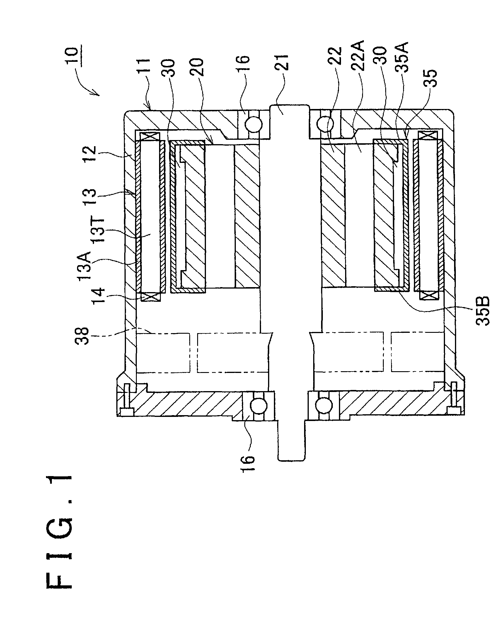
[0022][First Embodiment] The following provides an explanation of the invention based on FIGS. 1 to 3. A motor 10 shown in FIG. 1 is a brushless, three-phase alternating current motor, and a stator 11 of this motor 10 employs a structure in which a stator core 13 is fixed to the inside of a motor housing 12 by engaging therewith. The motor housing 12 has the form of, for example, a cylinder that is closed on both ends. In addition, the stator core 13 has a structure in which a plurality of teeth 13T are protruding to the inside from the inner peripheral surface of a cylindrical body 13A, and electromagnetic coils 14 are respectively wound around each of these teeth 13T.

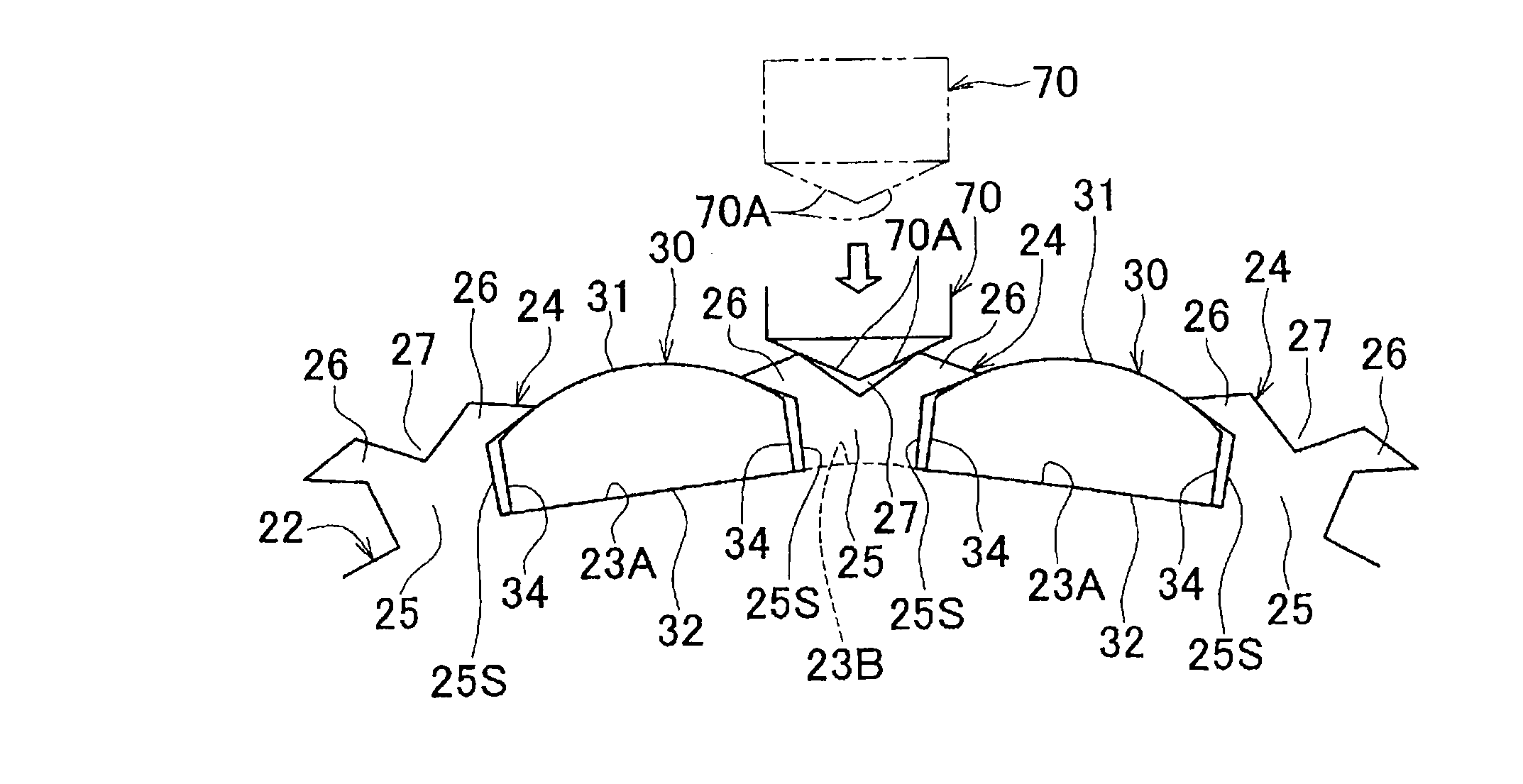
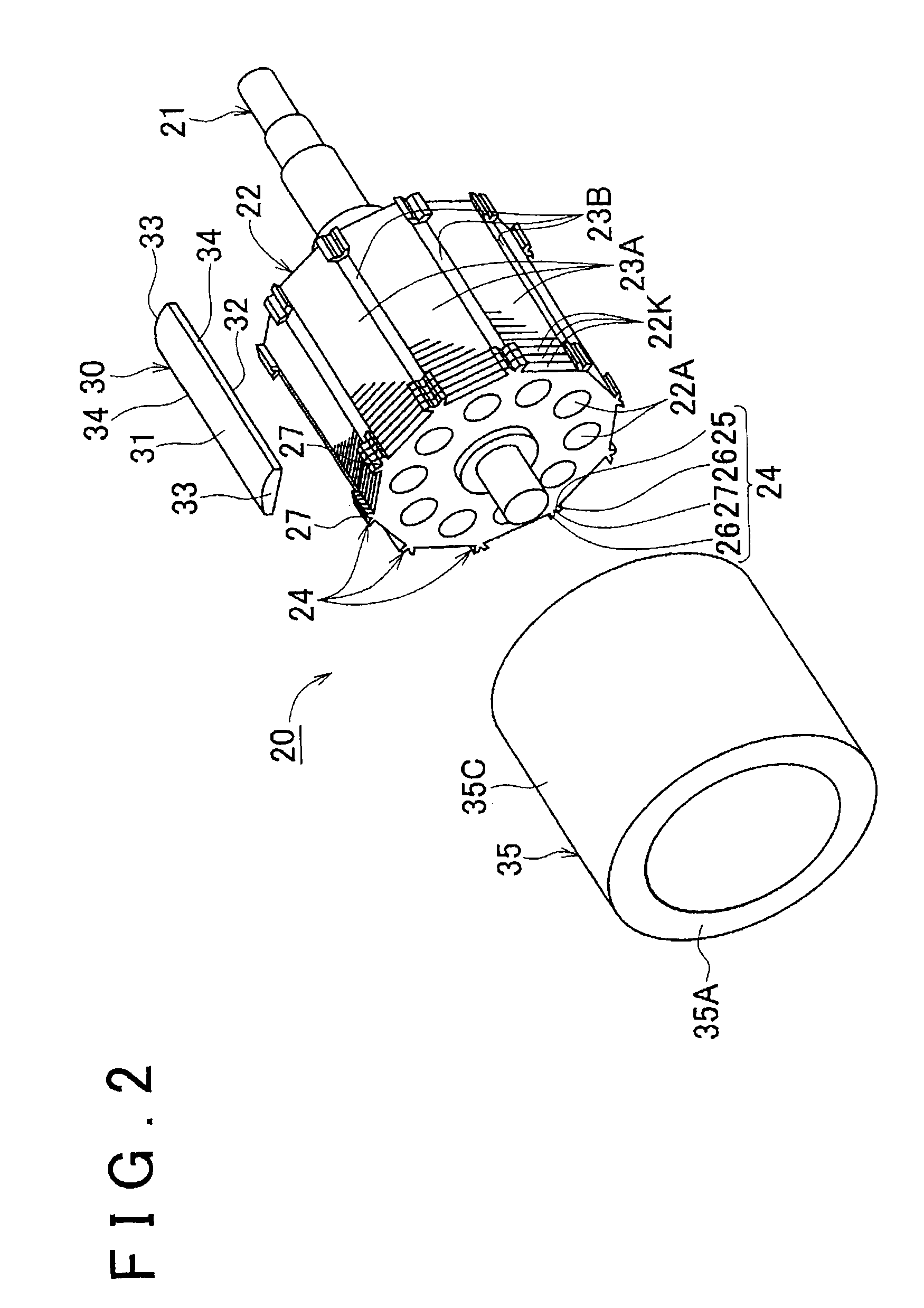
[0023]A rotor 20 of this motor 10 has a structure in which a rotor shaft 21 passes through the center of a rotor yoke 22, and a plurality of segment magnets 30 are fixed to the lateral surface of the rotor yoke 22. As shown in FIG. 2, the segment magnets 30 are roughly in the form of long plates extending in the axial...

second embodiment

[0041][Second Embodiment] The following provides an explanation of an embodiment of an electric power steering apparatus as claimed in the invention. As shown in FIG. 4, an electric power steering apparatus 100 of this embodiment is provided with a turning wheel connecting shaft 102 extending between a pair of turning wheels 101, 101 provided on a vehicle 110, and a shaft case 103 covering the outside of the turning wheel connecting shaft 102. Both ends of the turning wheel connecting shaft 102 are connected to each turning wheel 101, 101 via tie rods 102T, 102T, and the shaft case 103 is fixed to the chassis of the vehicle 110. In addition, a rack (not shown) is formed at an intermediate portion of the turning wheel connecting shaft 102, and a pinion (not shown) passing through the intermediate portion of the shaft case 103 from the side meshes with this rack.

[0042]A steering shaft 106 is connected to the upper end of the pinion, and a steering wheel 107 is further connected to the...


PUM

PropertyMeasurementUnit
widthaaaaaaaaaa
shapeaaaaaaaaaa
cylindrical shapeaaaaaaaaaa

Abstract

A motor rotor has: a rotor yoke; a plurality of magnet fixing sections formed on the lateral surface of the rotor yoke; segment magnets respectively fixed to the magnet fixing sections and extending in the axial direction of the rotor yoke; and a plurality of projections which are provided, on the rotor yoke, at each boundary section located between each of the adjacent magnet mounting sections, and which protrude outward from the rotor yoke; and a pair of end claws are formed by bifurcating the end of each projection into two prongs, and each of the end claws is locked to the outer surface of each of the segment magnets.

Description

INCORPORATION BY REFERENCE[0001]The disclosure of Japanese Patent Application No. 2008-109828 filed on Apr. 21, 2008 including the specification, drawings and abstract is incorporated herein by reference in its entirety.BACKGROUND OF THE INVENTION[0002]1. Field of the Invention[0003]The invention relates to a motor rotor provided with a plurality of segment magnets fixed on the lateral surface of a rotor yoke, an electric power steering apparatus using the motor as a drive source thereof, and a method for producing the motor rotor.[0004]2. Description of the Related Art[0005]An example of this type of motor rotor is available in which a plurality of segment magnets are fixed with an adhesive to the outer peripheral surface of a rotor yoke having a cylindrical shape (see, for example, Japanese Patent Application Publication No. 2003-230239 (JP-A-2003-230239)).[0006]However, since the coefficients of thermal expansion differ between the rotor yoke and the segment magnets, the adhesive...

Claims


Application Information

Patent Timeline
Patent Type & Authority Patents(United States)
IPC IPC(8): H02K21/12
CPCH02K1/278Y10T29/49012
Inventor ISHIKAWA, RYUJINAKANO, JIRO
Owner JTEKT CORP
Why Eureka
Try Eureka