Vehicle drive assist system

a technology of assist system and vehicle, which is applied in the direction of process control, pedestrian/occupant safety arrangement, instruments, etc., can solve the problems of short time the driver looks at the mirror, difficulty in recognizing the distance between the subject vehicle and the rear vehicle, and insufficient alarm provision, etc., to achieve the effect of improving the feeling of driving

Active Publication Date: 2012-06-19
SUBARU CORP
View PDF3 Cites 19 Cited by
  • Summary
  • Abstract
  • Description
  • Claims
  • Application Information

AI Technical Summary

Benefits of technology

[0008]In light of the situation, an object of the present invention is to provide a vehicle drive assist system that properly recognizes travel states of a front vehicle, a subject vehicle, and a rear vehicle, assists drive such that a subject vehicle position relative to the front vehicle and the rear vehicle becomes an optimum position corresponding to actual travel by taking into account drive states of the front vehicle and the subject vehicle and drive states of the subject vehicle and the rear vehicle, thereby improving feeling of drive.
[0010]With the vehicle drive assist system of the aspect, the travel states of the front vehicle, the subject vehicle, and the rear vehicle can be properly recognized, drive can be assisted such that the subject vehicle position relative to the front vehicle and the rear vehicle becomes an optimum position corresponding to actual travel by taking into account the drive states of the front vehicle and the subject vehicle and the drive states of the subject vehicle and the rear vehicle, thereby improving feeling of drive.

Problems solved by technology

However, the driver recognizes the rear vehicle only through a mirror, and a time the driver looks at the mirror must be short.
It is difficult to recognize a distance from the subject vehicle to the rear vehicle, a relative speed between the rear vehicle and the subject vehicle, and a brake operating state of the rear vehicle.
Regarding the above-mentioned problem, the above-described technique of the alarm device disclosed in Japanese Unexamined Patent Application Publication No. 2007-207047 controls the alarm by using the collision risk merely based on the relative positional relationship between the subject vehicle and at least one of the front and the rear vehicle, it is suspected that the alarm is not properly provided.

Method used


Image

  • Vehicle drive assist system
  • Vehicle drive assist system
  • Vehicle drive assist system

Examples


Embodiment Construction

[0017]An embodiment of the present invention will now be described with reference to the drawings.

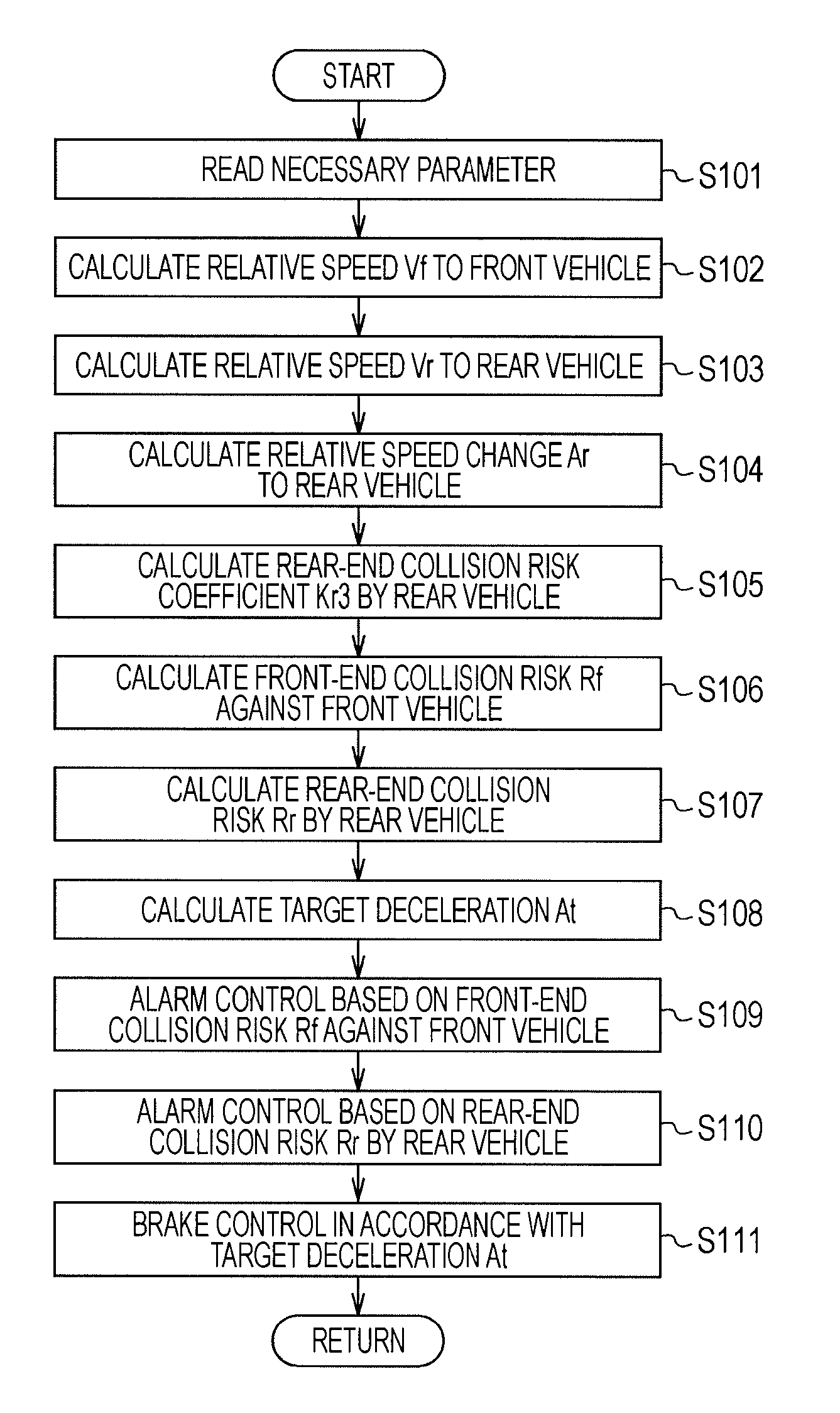
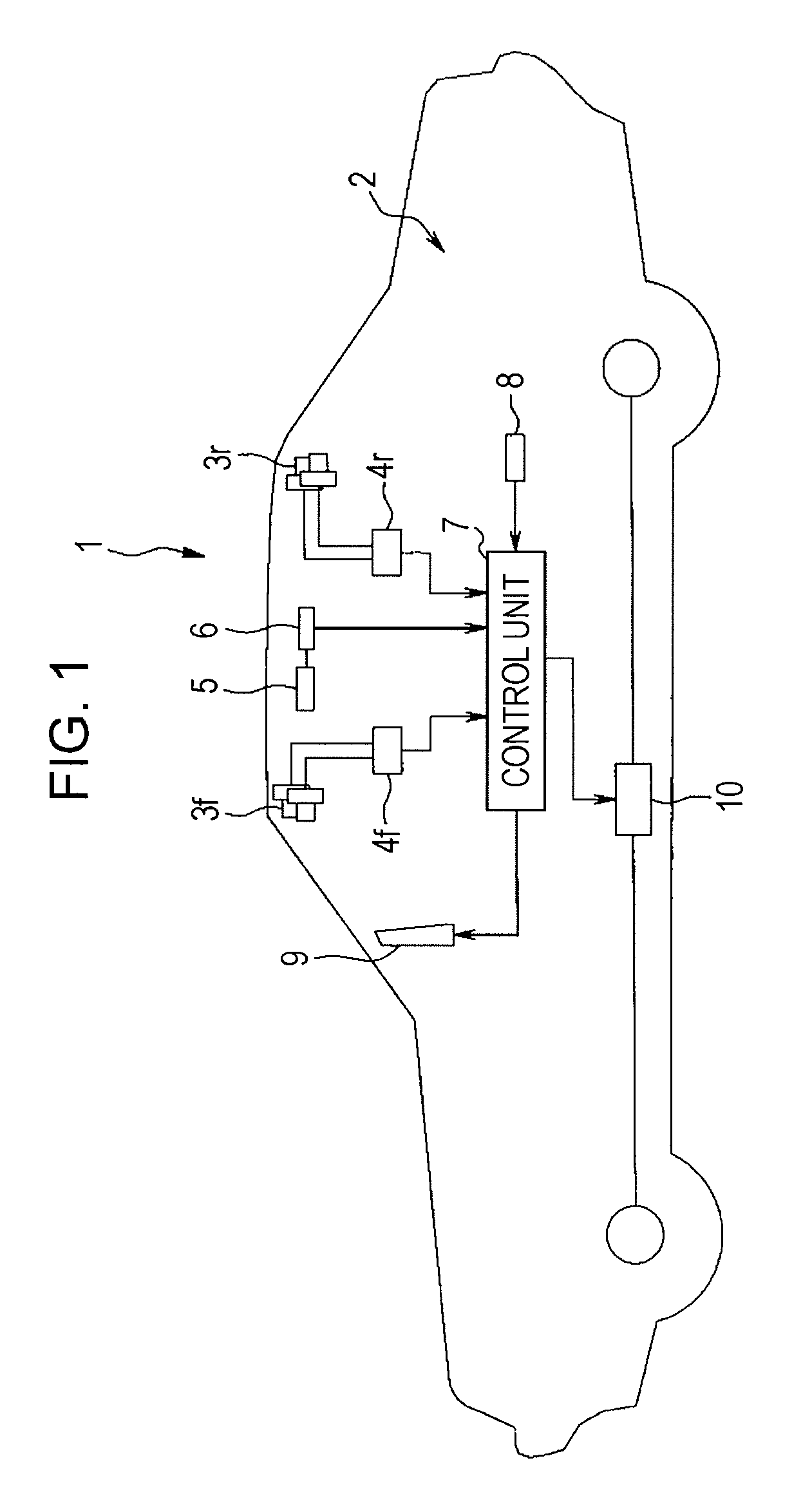
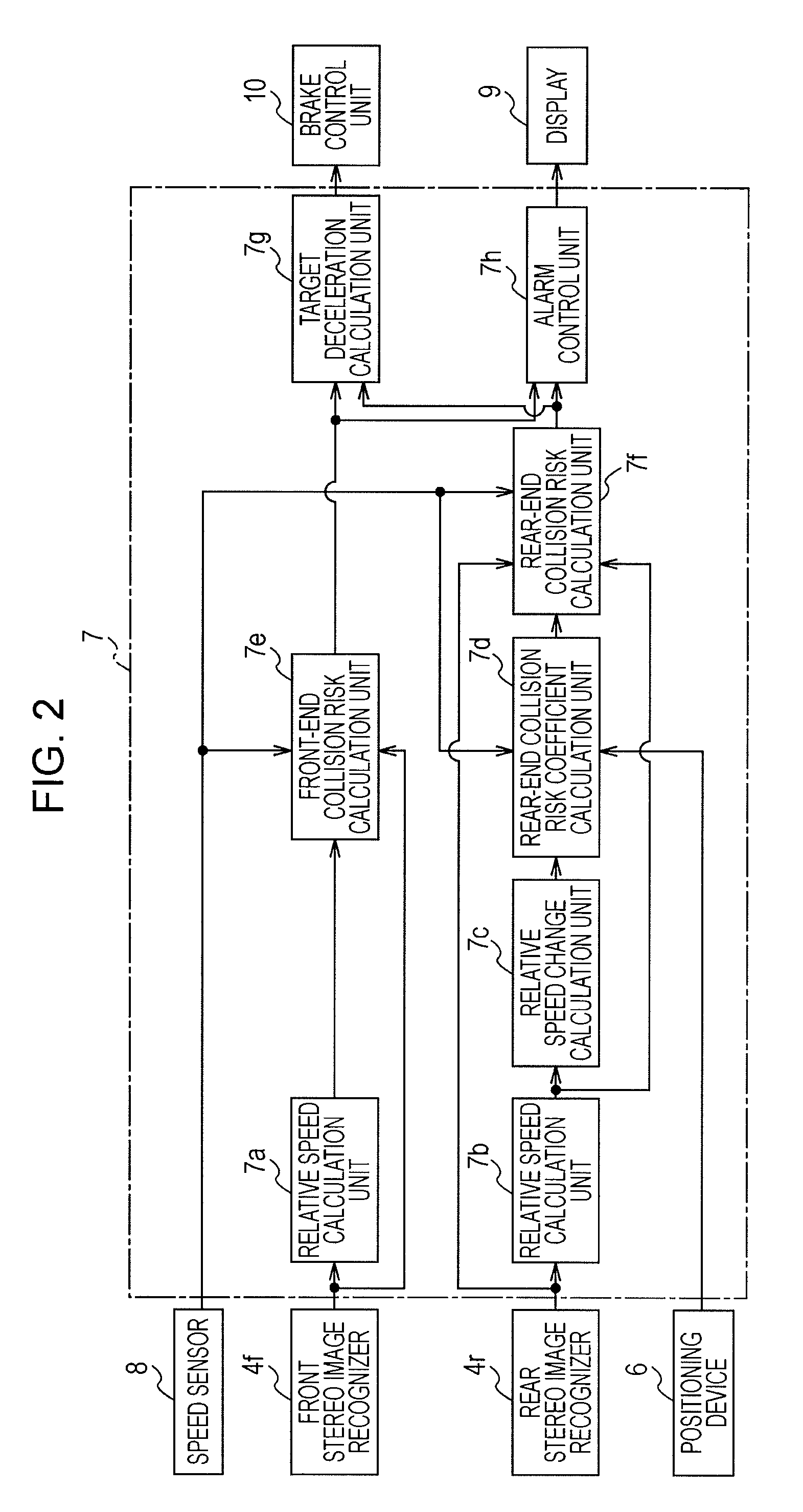
[0018]FIGS. 1 to 6 show an embodiment of the present invention. FIG. 1 is a configuration diagram briefly showing a drive assist system mounted on a vehicle. FIG. 2 is a functional block diagram of a control unit. FIG. 3 is a flowchart of a drive assist control program. FIG. 4 is an explanatory view showing an example relationship among a front vehicle, a subject vehicle, and a rear vehicle. FIG. 5 is a diagram showing setting of a rear-end collision risk coefficient by the rear vehicle. FIG. 6 is a diagram showing setting of a target deceleration correction amount.

[0019]In FIG. 1, a vehicle (subject vehicle) 1 of an automobile or the like has a drive assist system 2 mounted thereon. The drive assist system 2 mainly includes a front stereo camera 3f, a rear stereo camera 3r, a front stereo image recognizer 4f, a rear stereo image recognizer 4r, a communication device 5, a positioning de...


PUM


Abstract

A control unit sets a front-end collision risk of a subject vehicle against a front vehicle in accordance with a time headway of the subject vehicle and a margin time to front-end collision of the subject vehicle, and a rear-end collision risk of the subject vehicle by a rear vehicle in accordance with a time headway of the rear vehicle and a margin time to rear-end collision of the subject vehicle, the margin time to rear-end collision having a larger weight than that of the margin time to front-end collision in the front-end collision risk against the front vehicle. Brake control and alarm control are performed in accordance with the front-end collision risk against the front vehicle and the rear-end collision risk by the rear vehicle.

Description

CROSS REFERENCE TO RELATED APPLICATIONS[0001]The disclosure of Japanese Patent Application No. 2008-111599 filed on Apr. 22, 2008 including the specification, drawings and abstract is incorporated herein by reference in its entirety.BACKGROUND OF THE INVENTION[0002]1. Field of the Invention[0003]The present invention relates to a vehicle drive assist system that recognizes a front vehicle and a rear vehicle and prevents a subject vehicle from colliding with the front vehicle and the rear vehicle.[0004]2. Description of the Related Art[0005]In recent years, various techniques have been suggested for vehicles, the techniques which detect a front vehicle by using a front recognizer, such as a camera or a laser radar, and to avoid a subject vehicle from contacting the front vehicle, assist drive of the subject vehicle by providing a predetermined alarm or automatic brake control. Such techniques have been practically used. In addition, a technique has been suggested, which detects a rea...

Claims


Application Information

Patent Timeline
Patent Type & Authority Patents(United States)
IPC IPC(8): G05D1/02B60R21/00B60T7/12
CPCG08G1/16B60R2021/01259B60W30/09G08G1/165G08G1/166
Inventor MATSUNO, KOJI
Owner SUBARU CORP
Why Eureka
Try Eureka