Resilient high pressure metal-to-metal seal and method

a metal-to-metal seal, high-pressure technology, applied in the direction of sealing/packing, machine/engine, borehole/well accessories, etc., can solve the problems of ineffective seals, increased failure risk, and all seal replacements

Active Publication Date: 2012-06-26
WORLDWIDE OILFIELD MACHINE INC
View PDF34 Cites 24 Cited by
  • Summary
  • Abstract
  • Description
  • Claims
  • Application Information

AI Technical Summary

Benefits of technology

[0022]Accordingly, the present invention provides a resilient and / or flexible metal seal that may be utilized without deformation. In one embodiment, a seal ring comprises seal members that are pliable, and which may be bent repeatedly within their range of operation without injury or damage. The metal seal comprises a metal seal ring that is capable of returning to an original shape or position after having been compressed. Unlike many metal seals, the metal seal assembly components of an embodiment of the present invention may be taken apart and when put back together will seal.
[0024]The apparatus may comprise forming an undercut portion which may be positioned at a mid-section of the metal sealing ring. The undercut portion decreases the thickness of at least one metal wall on which the sealing surfaces are formed to thereby increase flexibility of the inner metal member and / or the outer metal member.

Problems solved by technology

Neither the operator nor the manufacturer will always know the conditions under which wellhead devices may be utilized, which increases the risk of failure.
One of the problems of soft metal seals is that all seals must be replaced whenever the wellhead device is opened.
Another problem is that these types of seals do not always make an initial seal, thereby necessitating opening up the wellhead device and replacing that seal as well as all other metal seals.
Moreover, small variations in the tolerances can render the seal ineffective.
To the extent resilient metal seals have been utilized, they are subject to problems in obtaining an initial seal and / or maintaining a seal with over wide pressure variations.

Method used


Image

  • Resilient high pressure metal-to-metal seal and method
  • Resilient high pressure metal-to-metal seal and method
  • Resilient high pressure metal-to-metal seal and method

Examples


Embodiment Construction

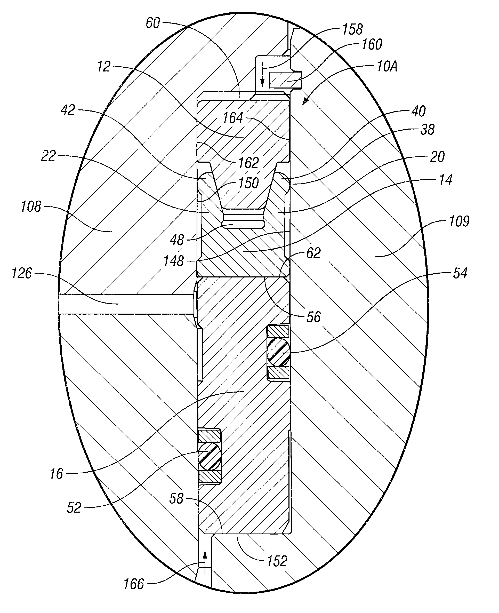
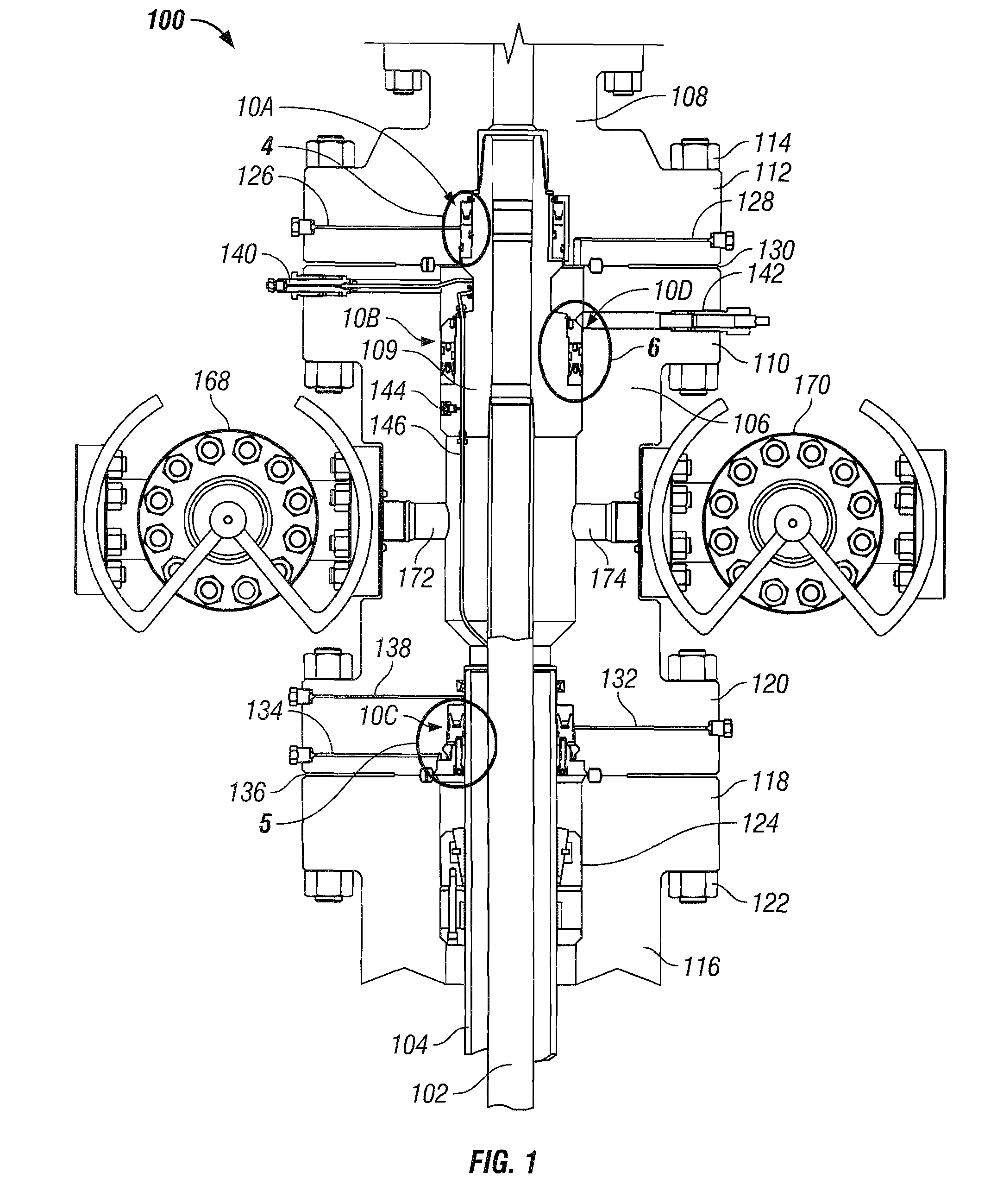
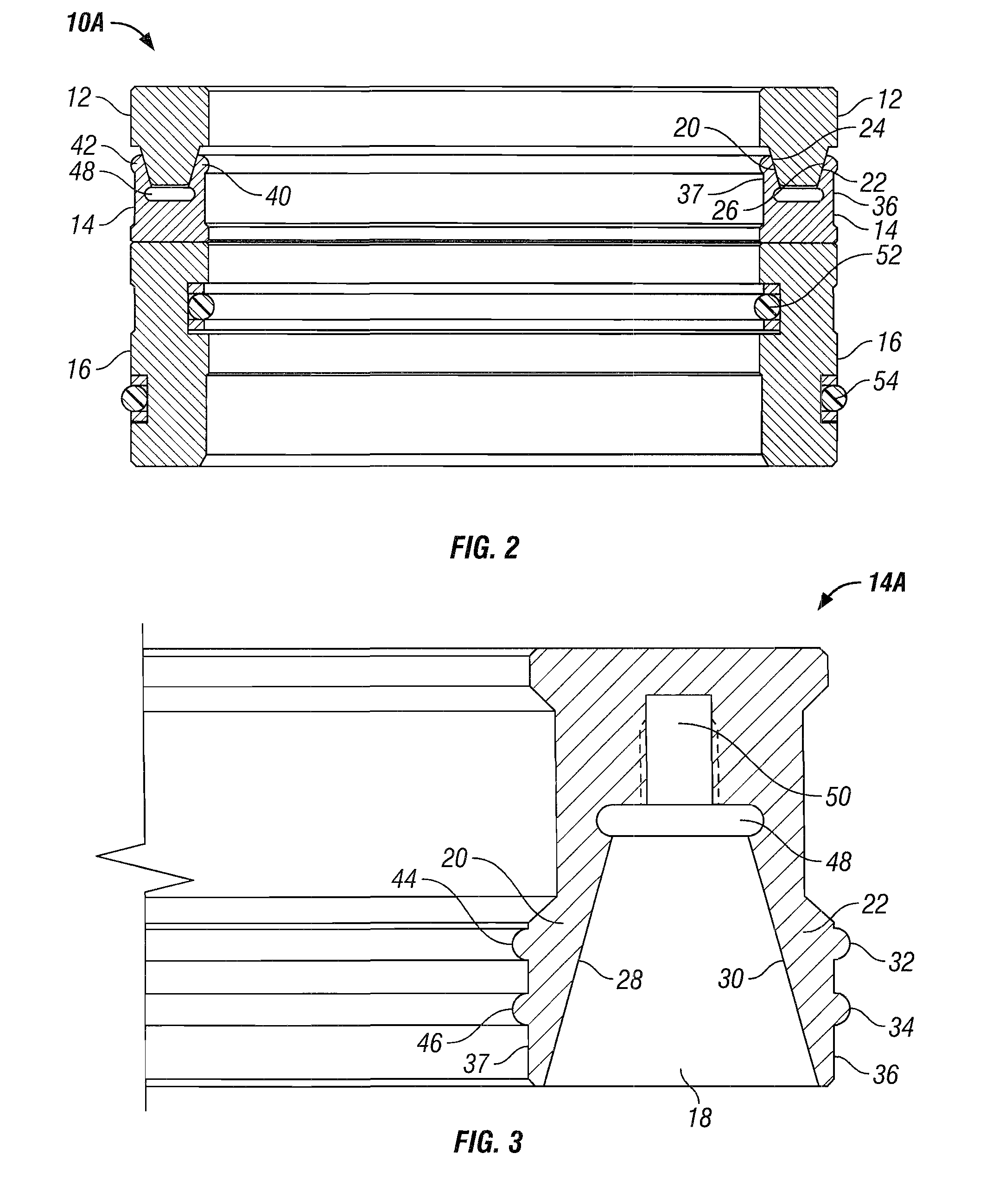
[0037]Referring now to the drawings and more particularly to FIG. 1, there is shown pressure control equipment 100 that is intended to be representative of various types of wellhead equipment, which may comprise wellheads, tubing assemblies, BOP's, spool assemblies, hanger assemblies, and the like. The present invention is not limited to use in pressure control equipment or to any particular pressure control equipment. Moreover, pressure control equipment 100 may comprise various additional components that are not shown.

[0038]Pressure control equipment 100 can be utilized to seal off a well to control fluids such as liquids and gasses. The fluids may be at high pressures or low pressures, may comprise a wide range of different fluids including acidic and caustic fluids, and may operate under a wide range of temperatures. In one embodiment of the present invention, a metal-to-metal sealing mechanism in accord with the present invention may be utilized to control pressures up to 30,00...


PUM

PropertyMeasurementUnit
pressuresaaaaaaaaaa
yield strengthaaaaaaaaaa
yield strengthsaaaaaaaaaa

Abstract

A high pressure metal-to-metal seal utilizes an expandable metal seal element able to withstand caustic fluids, high pressure, and high temperature. The metal-to-metal seal assembly is resilient for repeatable sealing and comprises an energizing metal ring and a metal sealing ring. Engagement of these two rings expands surfaces of the metal sealing ring to create inner and / or outer metal-to-metal seals.

Description

BACKGROUND OF THE INVENTION[0001]1. Field of the Invention[0002]The present invention relates generally to metal-to-metal seals and, more particularly, to a resilient metal-to-metal seal that in one embodiment may be mounted in a wellhead or BOP to control very high pressures, high temperature, and caustic fluids.[0003]2. Description of the Prior Art[0004]Metal-to-metal seals have advantages over non-metallic seals in that they operate over a wider range of temperatures, fluids, and pressures. Non-metallic seals of various materials are best matched to a particular range of temperatures, fluids, and pressures. Neither the operator nor the manufacturer will always know the conditions under which wellhead devices may be utilized, which increases the risk of failure.[0005]In the past, metal-to-metal seals have often been made of soft metals that deform to create a one-time-use seal. One of the problems of soft metal seals is that all seals must be replaced whenever the wellhead device ...

Claims


Application Information

Patent Timeline
Patent Type & Authority Patents(United States)
IPC IPC(8): E21B33/128F16L5/02F16J15/02
CPCE21B33/04F16J15/28F16J15/0887E21B2033/005Y10T29/49E21B2200/01
Inventor SUNDARARAJAN, ALAGARSAMY
Owner WORLDWIDE OILFIELD MACHINE INC
Why Eureka
Try Eureka