Photo interrupter

a technology of photo interrupter and photo plate, which is applied in the direction of optical elements, pulse techniques, instruments, etc., can solve the problems of reducing quality, affecting the efficiency of smt manufacturing, and affecting the quality of smt, so as to achieve the effect of efficiently forming the light emitting/receiving member and the housing

Inactive Publication Date: 2012-06-26
EVERLIGHT ELECTRONICS
View PDF6 Cites 12 Cited by
  • Summary
  • Abstract
  • Description
  • Claims
  • Application Information

AI Technical Summary

Benefits of technology

[0009]Thus, the photo interrupter of the invention forms the light emitting / receiving members and the housing efficiently, by using the first engaging portion, the second engaging portion, the first limiting portion and the second limiting portion.

Problems solved by technology

Thus, imprecise welding may occur due to human error, decreasing quality.
However, the SMT manufacturing process is relatively complicated.

Method used


Image

  • Photo interrupter
  • Photo interrupter
  • Photo interrupter

Examples


Embodiment Construction

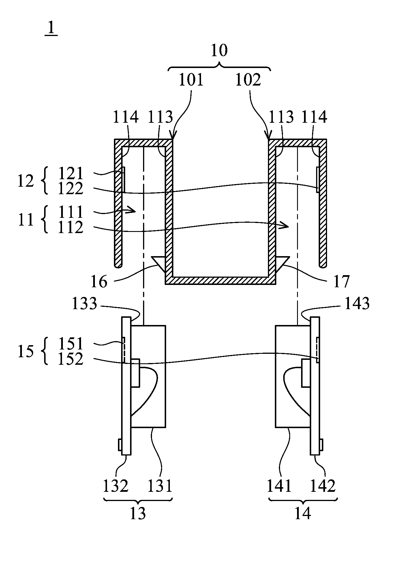
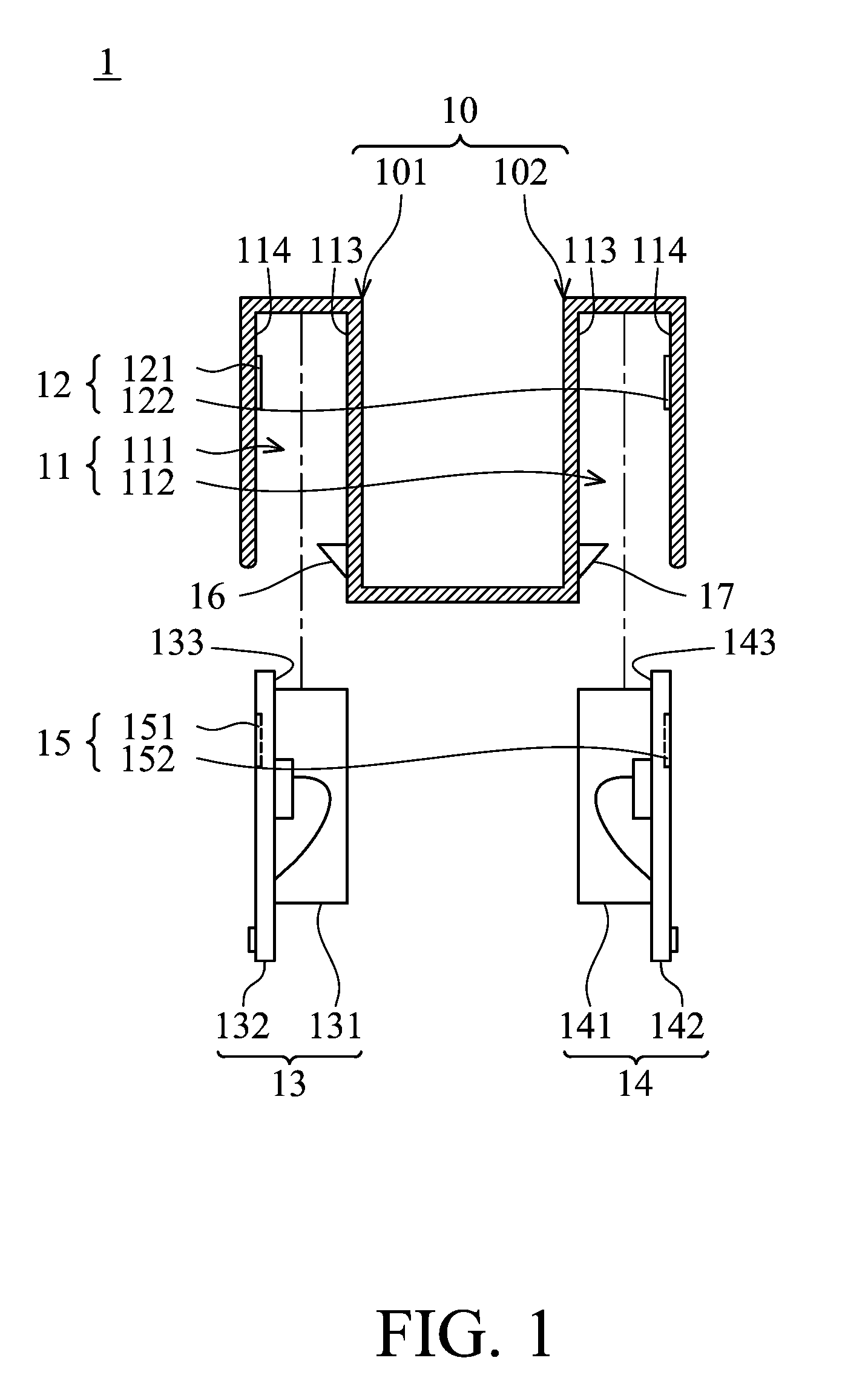
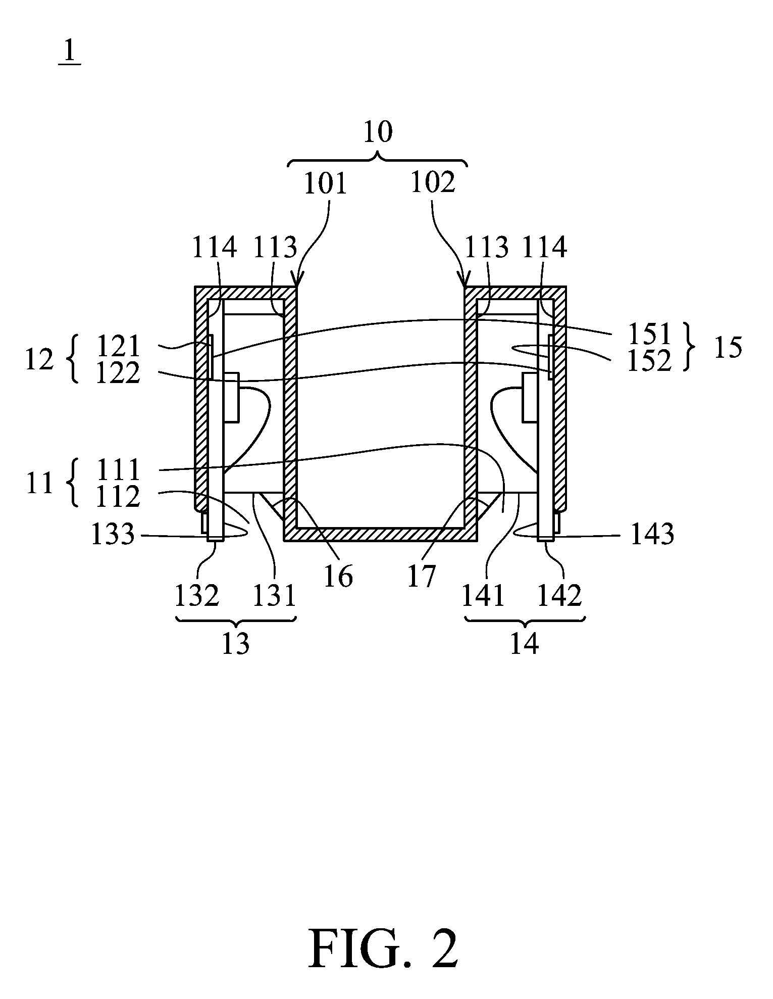
[0016]FIG. 1 and FIG. 2 are schematic views of a photo interrupter of the invention. Referring to FIGS. 1 and 2, the photo interrupter 1 comprises a housing 10 and a light emitting / receiving unit.

[0017]The housing 10 is formed integrally as a single piece and comprises a recess portion 11 and a first engaging portion 12. The housing 10 comprises a first housing 101 and a second housing 102. The first housing 101 and the second hosing 102 respectively define a first recess 111 and a second recess 112. Each of the first recess 111 and second recess 112 comprises a first surface 113 and a second surface 114 opposite to the first surface 113. The first engaging portion 12 comprises a first sub-engaging member 121 and a second sub-engaging member 122, respectively disposed on the second surface 114 of the first recess 111 and second surface 114 of the second recess 112.

[0018]The light emitting / receiving unit comprises a light emitting member 13, a light receiving member 14 and a second e...


PUM


Abstract

A photo interrupter is provided. The photo interrupter includes a housing and a light emitting / receiving unit. The housing defines a recess portion and has a first engaging portion disposed in the recess portion. The light emitting / receiving unit has a second engaging portion. When the light emitting / receiving unit is disposed in the recess portion, the first engaging portion engages with the second engaging portion.

Description

[0001]This Application claims priority of Taiwan Patent Application No. 098106807, filed on Mar. 3, 2009, the entirety of which is incorporated by reference herein.BACKGROUND OF THE INVENTION[0002]1. Field of the Invention[0003]The invention relates to a photo interrupter, and in particular, to a photo interrupter having efficient assembly.[0004]2. Description of the Related Art[0005]A photo interrupter is composed of a light emitting member and a light receiving member. The light emitting member emits light, and the light is received by the light receiving member to generate collector current. When an object passes between the light emitting member and the light receiving member, the collector current is reduced because the object disrupts the light. Thus, the object is detected by collector current changes.[0006]The light emitting / receiving members are usually formed by dual in-line package (DIP) or surface mounting technology (SMT). In the DIP Process, the components are first pl...

Claims


Application Information

Patent Timeline
Patent Type & Authority Patents(United States)
IPC IPC(8): G02B27/00
CPCH01L31/167H03K17/941H01L31/11H03K2217/94104
Inventor WANG, CHIN-HSUHSU, CHIH-HAOLIANG, CHUN-CHIH
Owner EVERLIGHT ELECTRONICS
Why Eureka
Try Eureka