
Biometric access control system

Active Publication Date: 2012-06-26
LAW ENFORCEMENT INTELLIGENT DEVICES
View PDF33 Cites 91 Cited by
  • Summary
  • Abstract
  • Description
  • Claims
  • Application Information

AI Technical Summary

Benefits of technology

"The present invention is an improved biometric access control system that combines the features of a standalone ID station / touch screen kiosk with multiple critical asset supporting racks and / or cabinets. The system uses RFID technology and wired or wireless communication to provide closed loop weapon tracking and user rated authorization and release of selected critical assets. The ID station / kiosk incorporates a sophisticated user interface processor driven protocol and operates with biometric input readers, RFID, and wired or wireless technology to provide user rated authorization and release of selected critical assets, maintenance tagging of selected items, and other database enterable / updatable logs for providing a history of weapon location and usage by selected individuals. The individual racks and lockers each represent a power enabling unit which includes a (120 V AC input and can hold a selected pluralities of critical assets. Each rack / locker can also include sensor verification of devices stored therein. The system is scalable and allows for simultaneous and overlapping access to all racks / lockers through a plurality of kiosks. The system also incorporates video cameras for recording user actions and pre-recorded video footage can be included as a clickable web link. Quality scores are given indicating the potential requirement for re-teaching poor quality of recorded fingerprint images."

Problems solved by technology

The Smart Locker design does not disclose use with any type of firearm, but teaches computerized tracking and monitoring of a plurality of lockers, based on multiple levels of security.

Method used


Image

  • Biometric access control system
  • Biometric access control system
  • Biometric access control system

Examples


Embodiment Construction

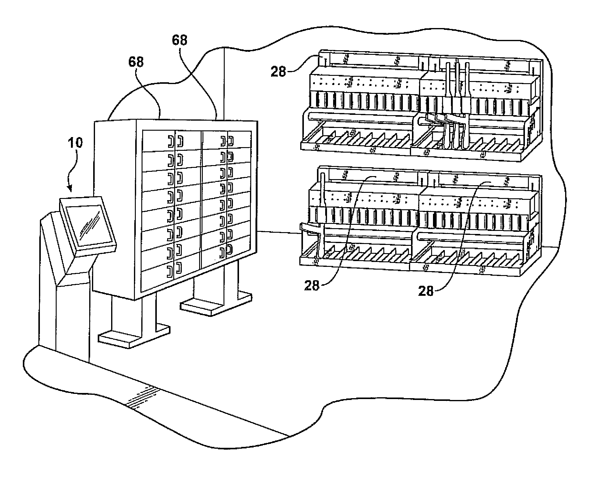
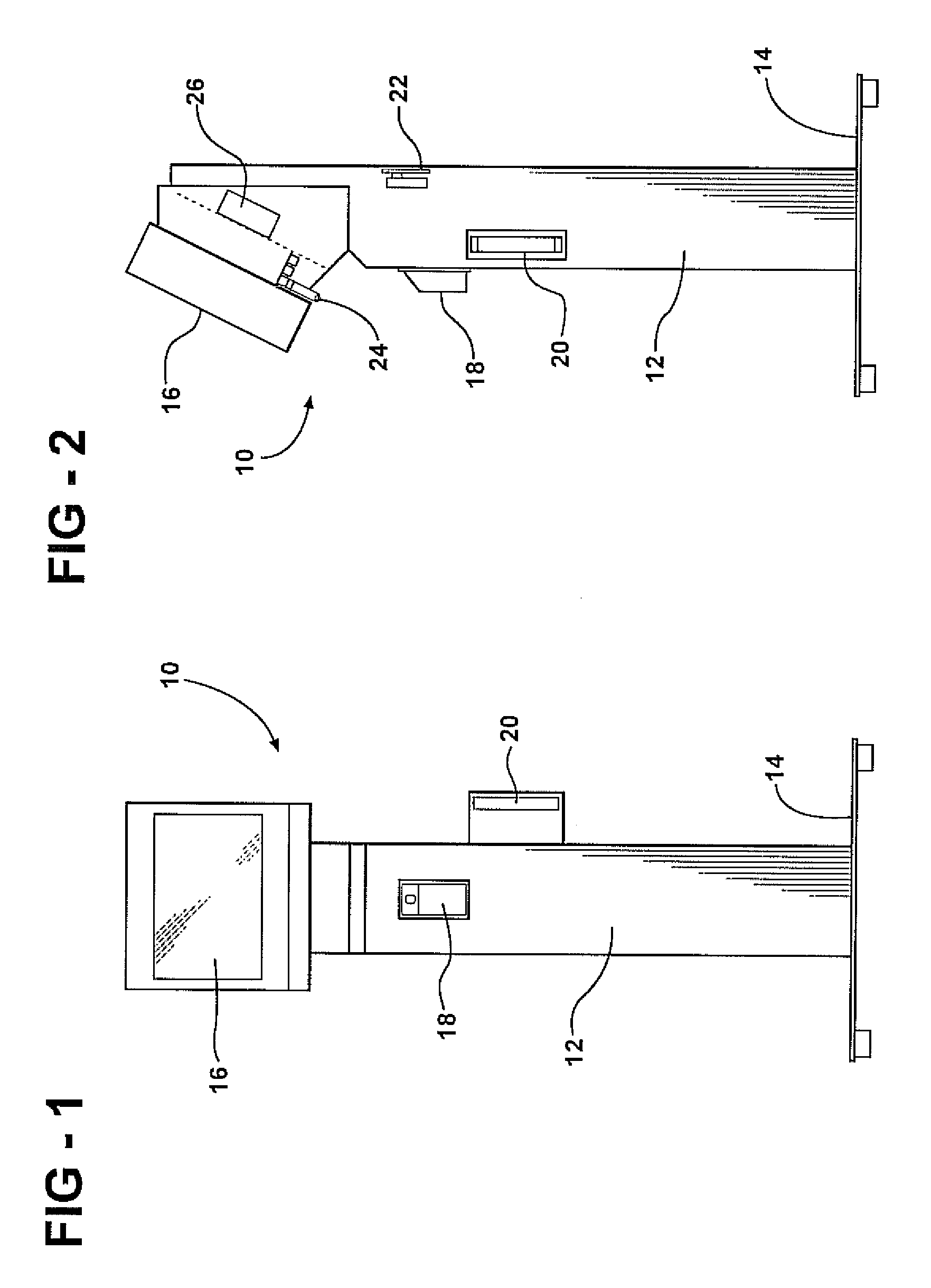
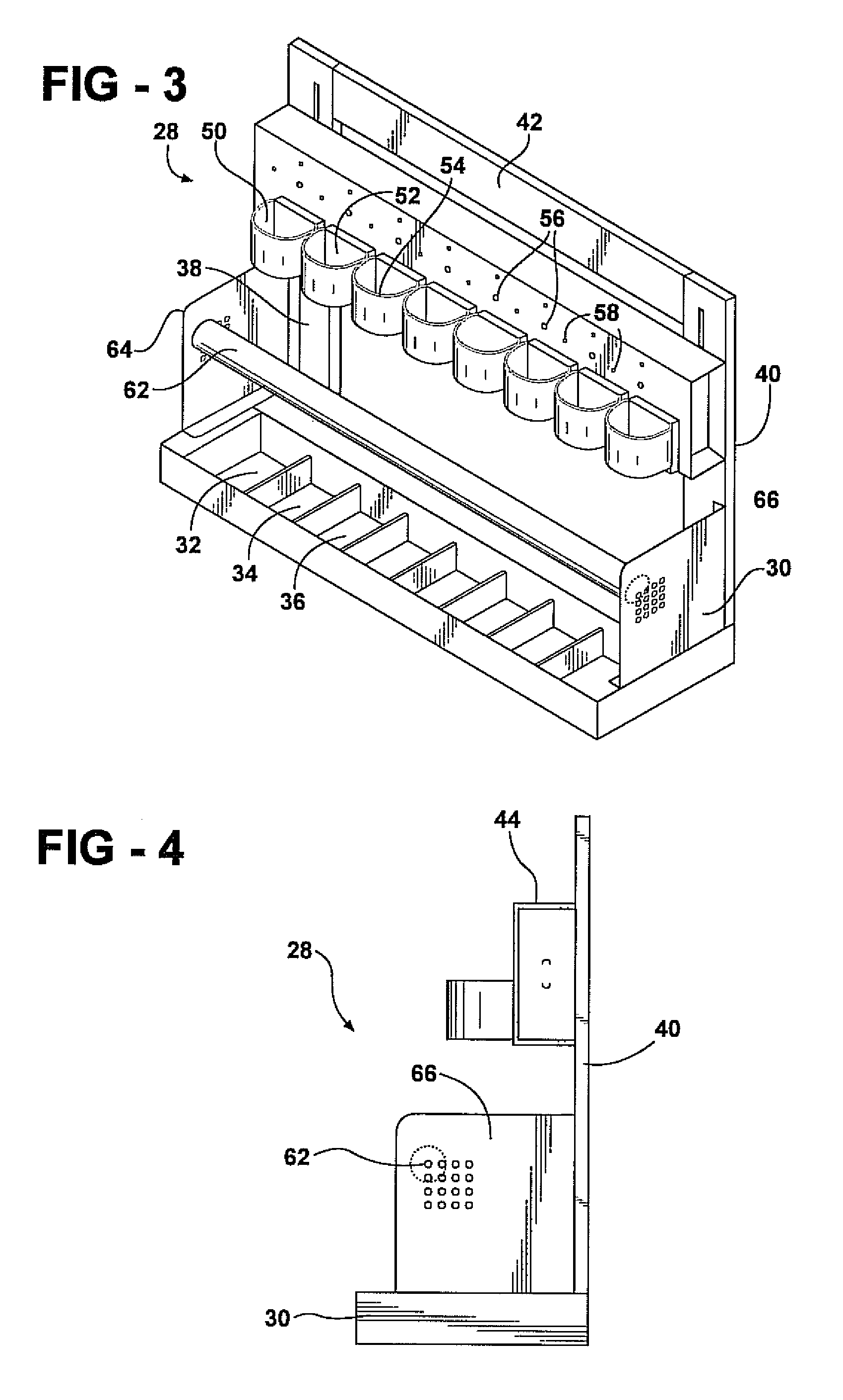
[0058]Referring now to the various illustrations, a biometric access control system (BACS) is illustrated according to a preferred embodiment of the present invention. As previously described, the present invention combines the features of a stand-alone ID station / touch screen kiosk with a plurality of individual critical asset (e.g. weapon) supporting racks and / or cabinets, these being communicable in two way fashion via a wired or wireless (Bluetooth) technology with the ID station and in order to authorize release and re-entry of such items. The control system further provides for more efficient and accurate recordkeeping of asset acquisition / return / maintenance identification and avoids the needs for manually generated paper logs. With further regard to the biometric user input requirement and the associated user interface manual, the ability to track and verify location and condition of a given asset is simplified, with the ability to generate reports and to allow for user / equip...


PUM


Abstract

A biometric access control system for tracking critical assets and including an ID station incorporating a biometric input reader, an RFID antenna and reader and a wired or wireless (Bluetooth) communication device. A remotely positioned structure includes either or both of a rack or a locker for holding a plurality of the critical assets in individually locked fashion. A processor control built into the ID station operatively actuates each of a plurality of individual locking mechanisms incorporated into the rack structure or locker, in response to successive biometric and weapon selection inputs communicating with the processor, and for determining at least one of user identification and weapon release authorization prior to the processor actuating the locking mechanism to release the weapon. An associated computer writeable medium operates with the processor and establishes a series of subroutines for establishing user identification, weapons rating, selective weapon release / reentry and associated maintenance and record keeping log reports.

Description

CROSS-REFERENCE TO RELATED APPLICATIONS[0001]The present application claims the priority of U.S. patent application Ser. No. 11 / 183,473, filed Jul. 18, 2005, and entitled Stand-Alone Weapons Storage and Locking Rack with Biometric Input and Processor Driven Release Authorization, Maintenance and Inventory Control.BACKGROUND OF THE INVENTION[0002]1. Field of the Invention[0003]The present invention relates generally to both wired and wireless related variants of weapon storage and access assemblies. More specifically, the present invention discloses an improved weapon release assembly which combines the features of computerized rating and release / reentry of any number of weapons based upon individual biometric input parameters. Features include a standalone touch screen kiosk with built-in biometric reader, built-in RFID antenna and reader, Bluetooth network master and web server for remote connections, as well as alternate hard wired versions, and which communicates with any combina...

Claims


Application Information

Patent Timeline
Patent Type & Authority Patents(United States)
IPC IPC(8): G06F7/04
CPCG07C9/00158G06K9/00006Y10T70/7441G07C9/37G06V40/12G07C9/253G07C9/28A47B81/005E05B73/00
Inventor CRIGGER, RICKFOSTER, DAVEHOFF, SAM
Owner LAW ENFORCEMENT INTELLIGENT DEVICES
Learn More