
Eco-drive assist apparatus and method

a technology of eco-drive and assist device, which is applied in the direction of identification means, instruments, process and machine control, etc., can solve the problems of mismatch between eco-drive information and information showing the working state of the engine, and confuse the driver, and achieve the effect of reliable or comfortable eco-driv

Active Publication Date: 2012-06-26
FUJITSU GENERAL LTD
View PDF8 Cites 11 Cited by
  • Summary
  • Abstract
  • Description
  • Claims
  • Application Information

AI Technical Summary

Benefits of technology

The present invention provides an eco-drive assist apparatus and method that can help drivers in hybrid vehicles achieve more reliable and comfortable eco-drive. The apparatus calculates the quantity of eco-drive based on the vehicle's power and displays it in a graphic manner relative to a threshold value that indicates whether the engine is started up or not. This allows drivers to easily see the degree of ecology and economy in driving. The display change threshold value is set to match the engine startup threshold value, which ensures that the display is changed from one state to the other when the engine is started up or not. This improves the accuracy and reliability of the eco-drive assist apparatus.

Problems solved by technology

When the engine has been started up although the eco-drive information shows the eco-drive state, there is a mismatch between the eco-drive information and the information showing the working state of the engine.
This mismatch may confuse the driver.

Method used


Image

  • Eco-drive assist apparatus and method
  • Eco-drive assist apparatus and method
  • Eco-drive assist apparatus and method

Examples


Embodiment Construction

[0019]A description will now be given of embodiments with reference to the accompanying drawings.

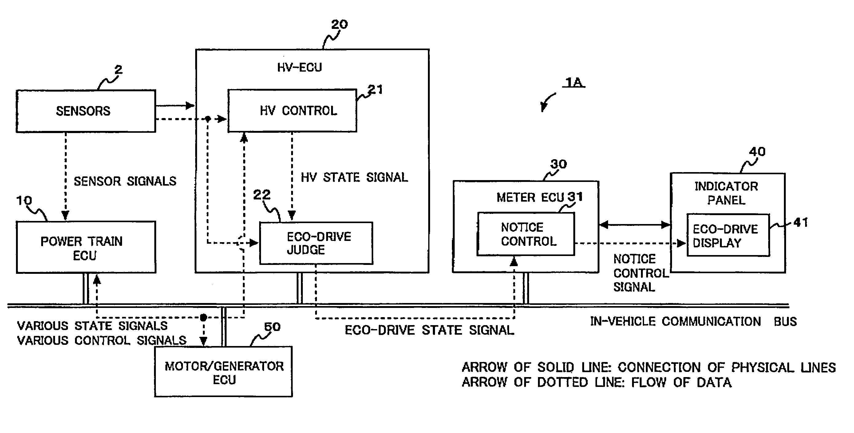
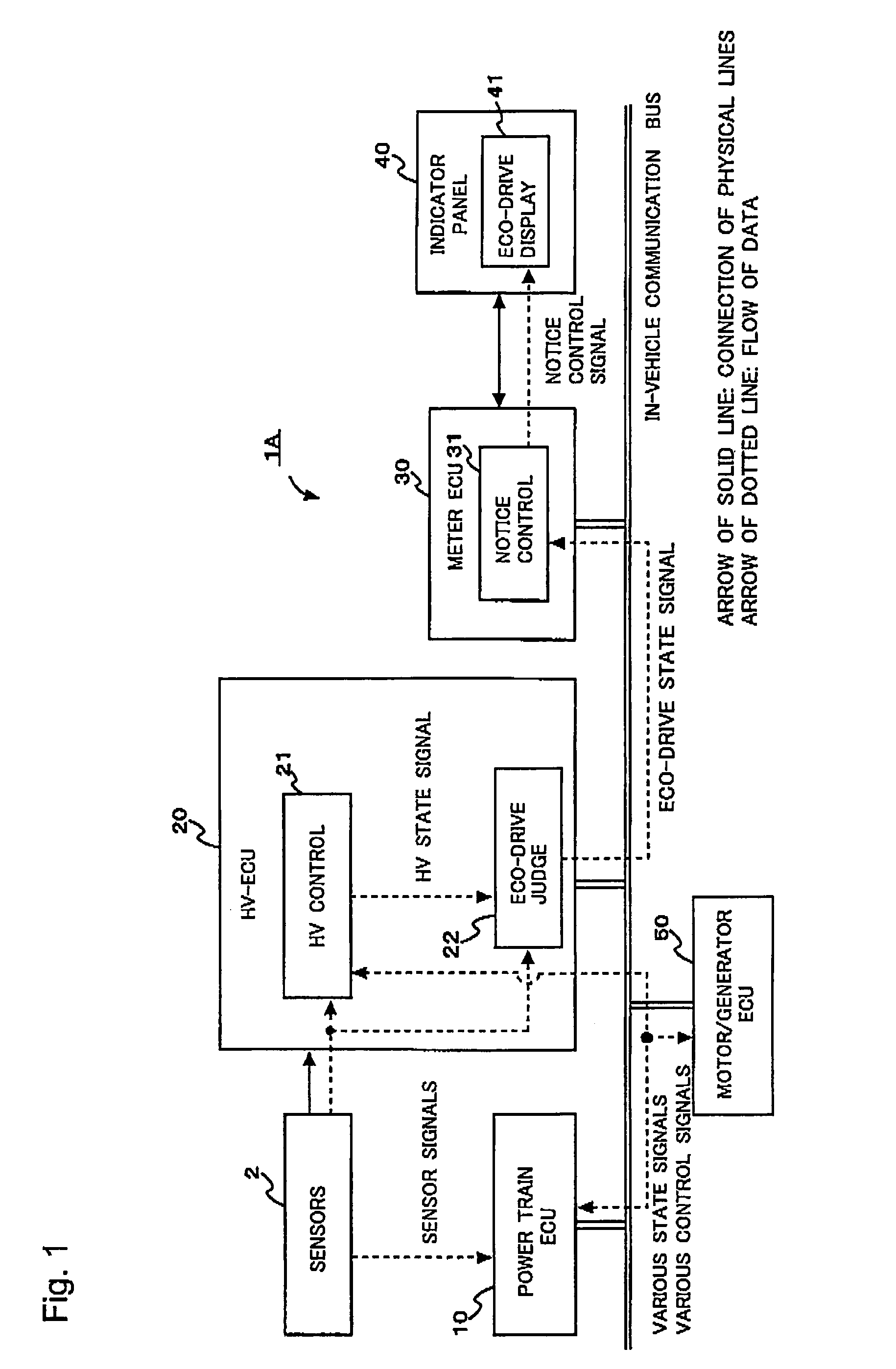
[0020]FIG. 1 is a block diagram of an eco-drive assist system 1A that assists the driver in eco-drive. The term “eco” is defined as a term that includes at least one of economy and ecology. The term “economy” means reduction in consumption of fuel and thus saves fuel, and the term “ecology” means reduction in consumption of fossil fuel and suppression of generation and emission of toxic substance and carbon dioxide, which may be caused when fossil fuel is burned.

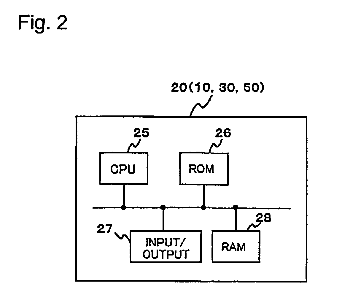
[0021]The eco-drive assist system 1A includes a power train ECU (electronic control unit) 10, a hybrid ECU (HV-ECU) 20, a meter ECU 30, and a motor / generator ECU 50, all of which ECUs are connected by an in-vehicle communication bus. The power train ECU 10 controls an engine and a transmission. The hybrid ECU 20 controls a hybrid system. The meter ECU 30 controls display on an indicator panel 40. The motor / generator ECU 50 contro...


PUM


Abstract

An eco-drive assist apparatus that displays a quantity of eco-drive that indicates a degree of ecology and / or economy in driving in a hybrid vehicle equipped with an engine and a motor, includes: a first part configured to calculate the quantity of eco-drive on the basis of a vehicle power generated in the vehicle; and a second part configured to cause the quantity of eco-drive to be displayed in a graphic manner as a relative quantity to an eco-drive judgment threshold value that indicates whether the vehicle is in an eco-drive state and to cause the quantity of eco-drive to be displayed in a graphic manner as a relative quantity to an engine startup threshold value that indicates whether the engine is started up. The second part controls a display of the quantity of eco-drive in the graphic manner as the relative quantity to the engine startup threshold value on the basis of a first display change threshold value that changes the display from a first display showing that the engine has not been started up to a second display showing that the engine has been started up and a second display change threshold value that changes the display from the second display to the first display. The first display change threshold value is the engine startup threshold value.

Description

FIELD[0001]The present invention relates to an apparatus and a method for assisting the driver in eco-drive.BACKGROUND[0002]Recently, some vehicles have been equipped with an eco-drive assist apparatus for assisting the driver in eco-drive in view of environmental protection. The eco-drive assist apparatus determines whether the vehicle is traveling efficiently in fuel economy by checking various factors, which may include the degree of depressing the accelerator pedal, the efficiency of the engine and transmission, the traveling speed and the accelerated velocity. When the vehicle is traveling efficiently in fuel economy, the vehicle is in an eco-drive state. When it is determined that the vehicle is in the eco-drive state, an LED (light emitting diode) may be turned ON. The fuel economy may be calculated at an instantaneous time in traveling and may be indicated as an instantaneous fuel efficiency.[0003]Japanese Patent Application Publication No. 2000-205925 proposes displaying a ...

Claims


Application Information

Patent Timeline
Patent Type & Authority Patents(United States)
IPC IPC(8): B60Q1/00B60L50/16
CPCB60L11/123B60W10/06B60W10/08B60W10/10B60W50/14B60L15/2045Y02T10/7283B60L2240/486B60L2250/12B60L2250/16B60W20/00B60W2510/0604B60W2520/10B60W2540/10B60W2540/16B60Y2200/90Y02T10/6217Y02T10/6286Y02T10/7077Y02T10/72B60L50/61Y02T10/62Y02T10/64Y02T10/70B60W2050/146B60W2050/004B60W2510/06B60W50/04Y02T10/7072
Inventor WATANABE, MASATOSHIISHIO, MASATOTOMIYAMA, KOHICHIMATSUO, TOMOHIROSAITO, KAN
Owner FUJITSU GENERAL LTD
Learn More