
User adjustable prosthetic ankle that compensates for different heel heights
a prosthetic ankle and adjustable technology, applied in the field of ankle prosthesis, can solve the problems of unsafe limb, unnatural gait, user is limited to proscribed prosthetic legs with fixed angles,
- Summary
- Abstract
- Description
- Claims
- Application Information
AI Technical Summary
Benefits of technology
Problems solved by technology
Method used
Image

Examples
Embodiment Construction
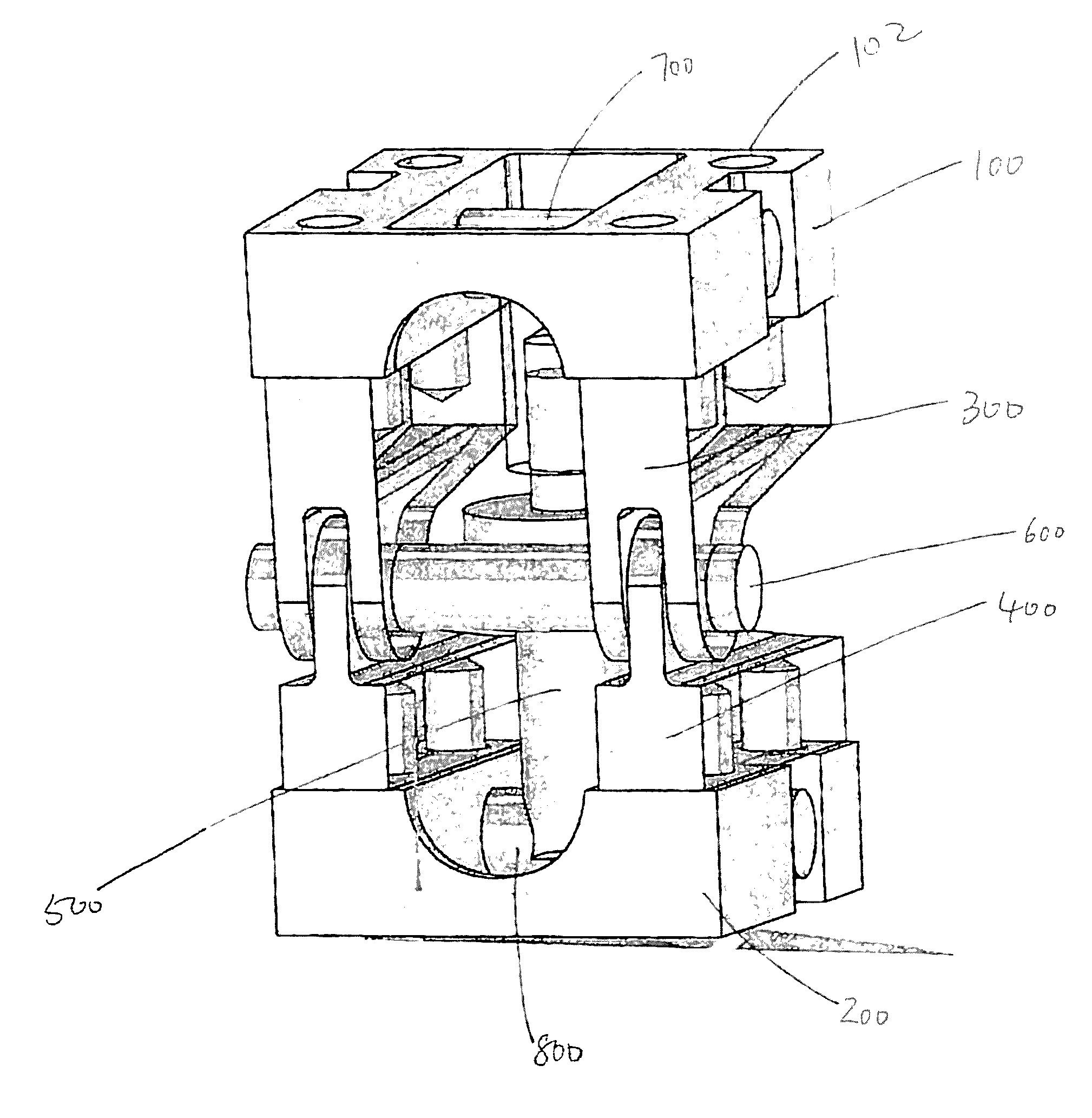
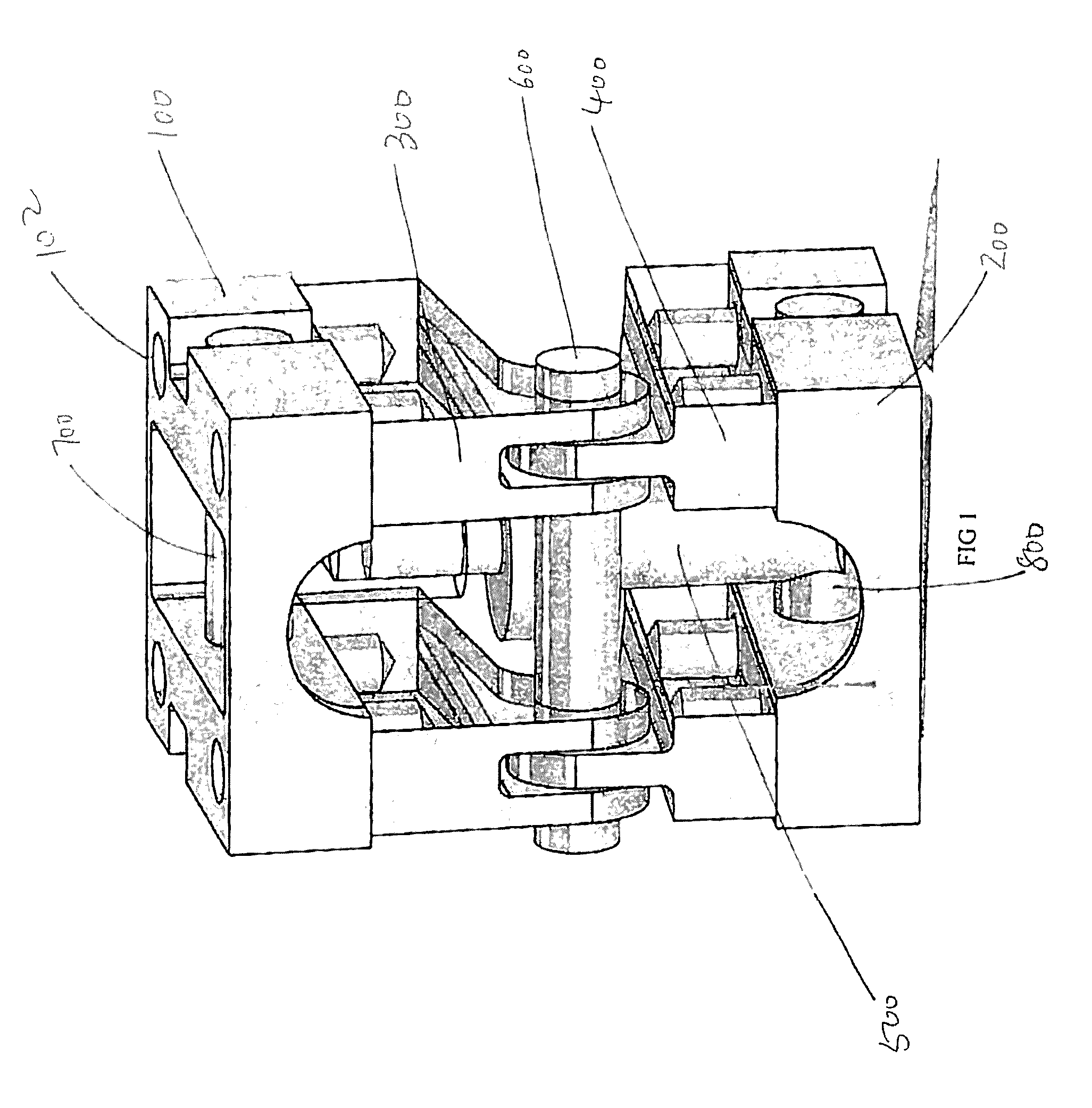
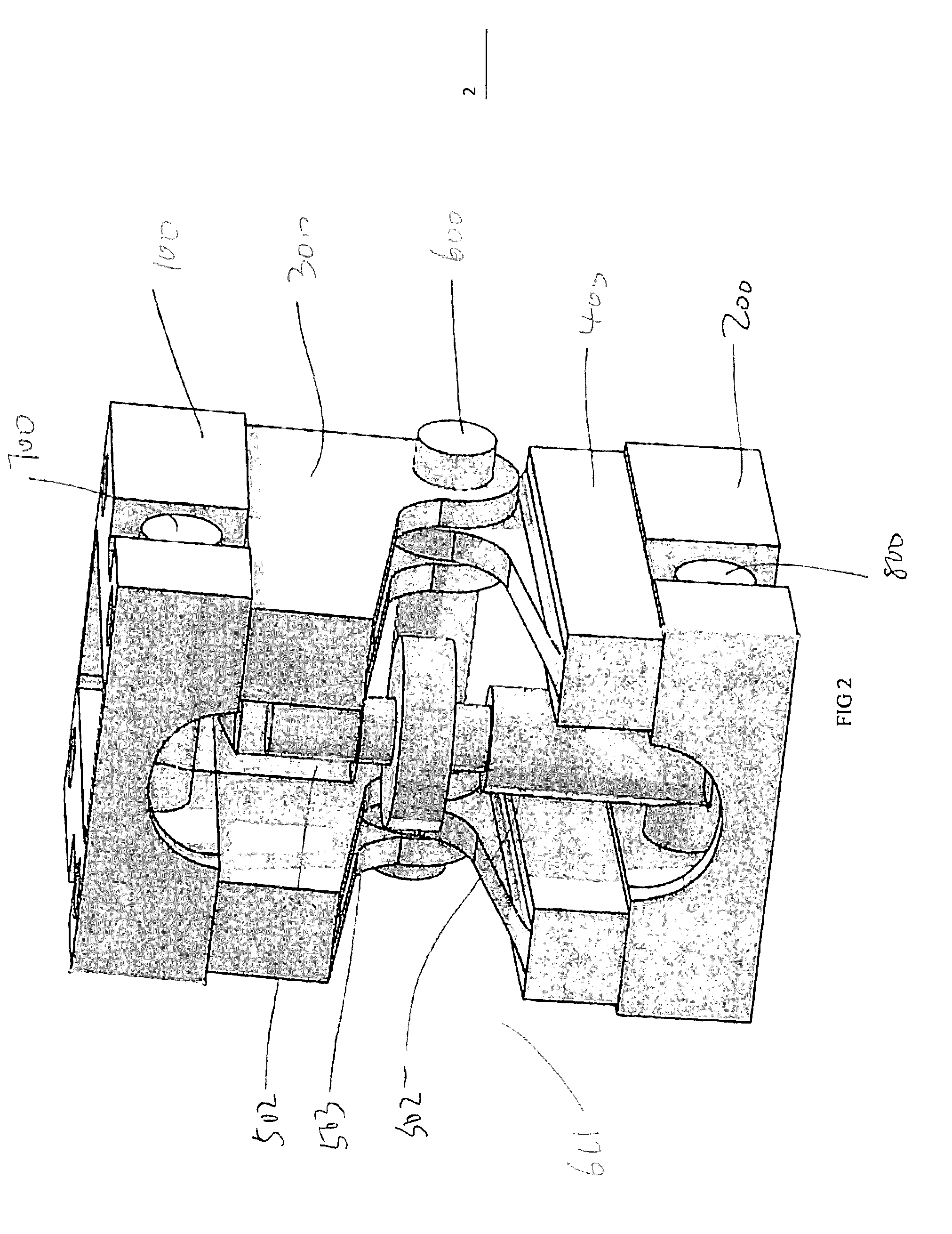
[0031]Referring to FIG. 1-5, a prosthetic ankle of the present invention comprises an upper base unit 100 for rigidly connecting to the leg, shin or stump component of a prosthetic leg; a lower base unit 200 for rigidly connecting to the foot component of a prosthetic leg; a pair of upper wing units 300, which are rigidly connected to the upper base unit 100; a pair of lower wing units 400 that are rigidly connected to the lower base unit 200. The upper 300 and lower wing 400 units are engaged and restrained to each other on one side, while allowing rotational movement relative to each other the opposite side. The upper and lower base units have a top surface and bottom surface, whose area is at least two inches by two inches. The upper and lower base unit also have a thickness, which forms a continuous side. A turnbuckle assembly 500 is disposed between the upper base unit 100 and the lower base unit 200, which can extend or contract to change the angle between the upper base unit ...
PUM
 Abstract
Description
Claims
Application Information