Building frame construction tools and methods using laser alignment

a technology for building frames and construction tools, applied in the direction of instruments, movable markers, writing aids, etc., can solve the problems of inaccurate production, irregular marks, and dry lines that are prone to error and inaccuracy, and achieve accurate and convenient operation, easy installation, and the effect of accurate results

Inactive Publication Date: 2012-07-03
TRI WALKER
View PDF48 Cites 37 Cited by
  • Summary
  • Abstract
  • Description
  • Claims
  • Application Information

AI Technical Summary

Benefits of technology

[0012]The invention comprises a building frame-construction tool system, and methods of using some or all of the tools of said tool system, for example, for wall and roof construction and / or for building layout. The system preferably comprises a laser light unit that comprises a plurality of adjustments for directing the laser light in a variety of directions, preferably for vertical, horizontal, and pivotal adjustment. The laser light preferably comprises a hook or clamp with a gripping surface for easy installation on a rafter or other frame member, and may comprise rotary and / or linear encoding and display for extremely accurate and convenient operation.

Problems solved by technology

Such a chalk line, if handled in-expertly and / or in windy weather, may produce inaccurate, irregular marks, wherein the rafters can end up being cut to different lengths or wherein the builder has to proceed slowly to try to estimate and correct the inaccuracies.
Likewise, a dry line is prone to error and inaccuracy, especially if stretched / pulled a great distance.
Using a dry line high up in the air and / or in windy weather, and / or on wet, snow or ice-covered surfaces, can be frustrating, slow, and even more inaccurate than a chalk line.

Method used


Image

  • Building frame construction tools and methods using laser alignment
  • Building frame construction tools and methods using laser alignment
  • Building frame construction tools and methods using laser alignment

Examples


Embodiment Construction

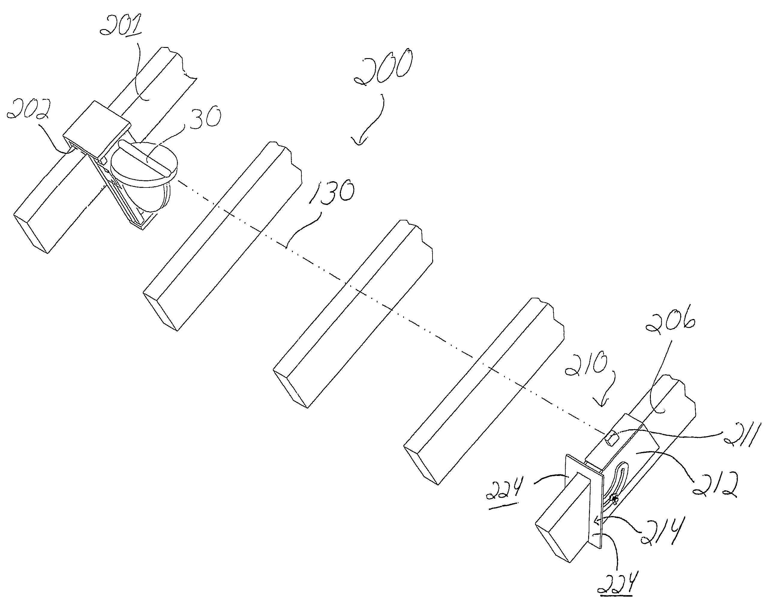
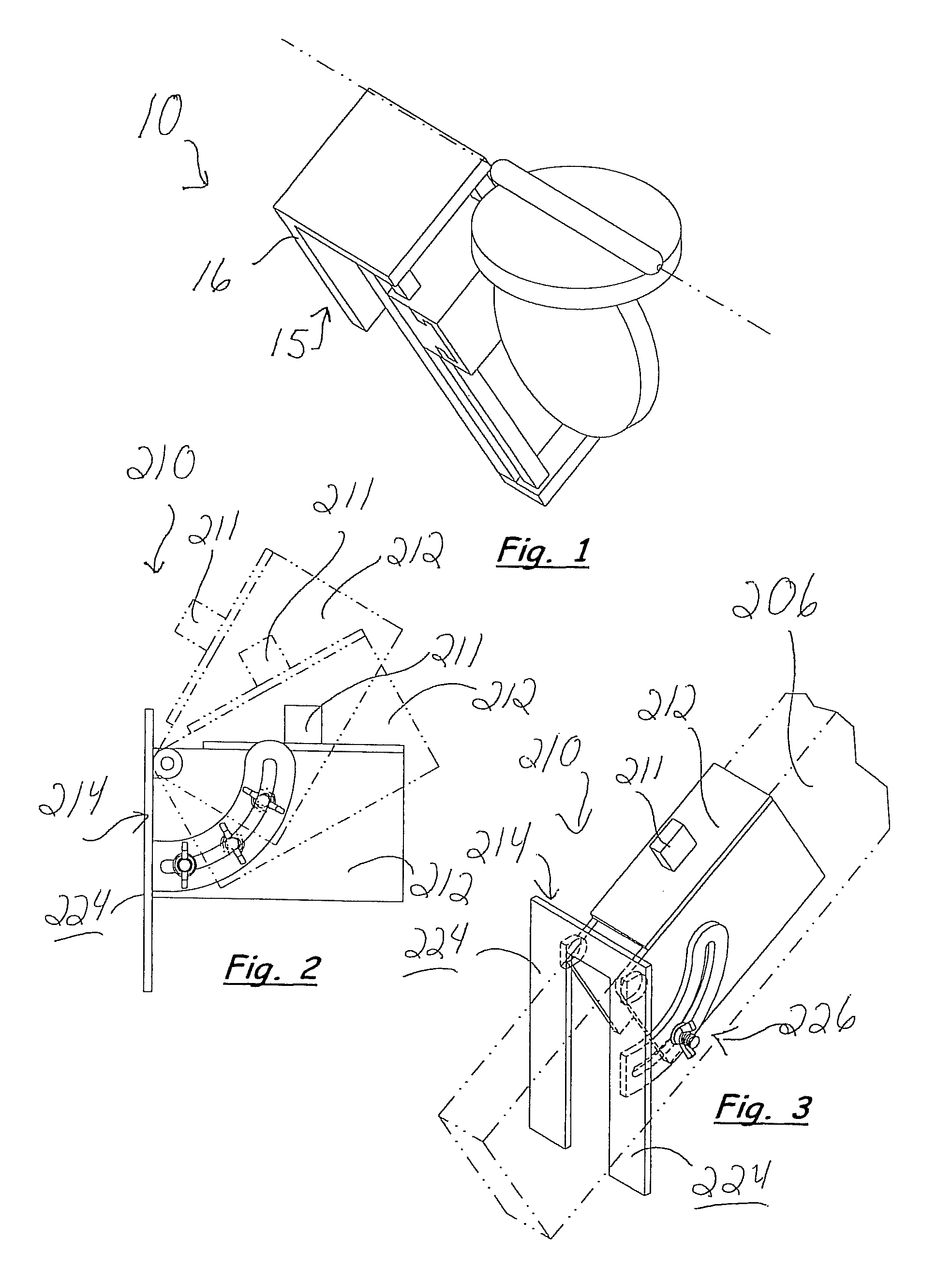
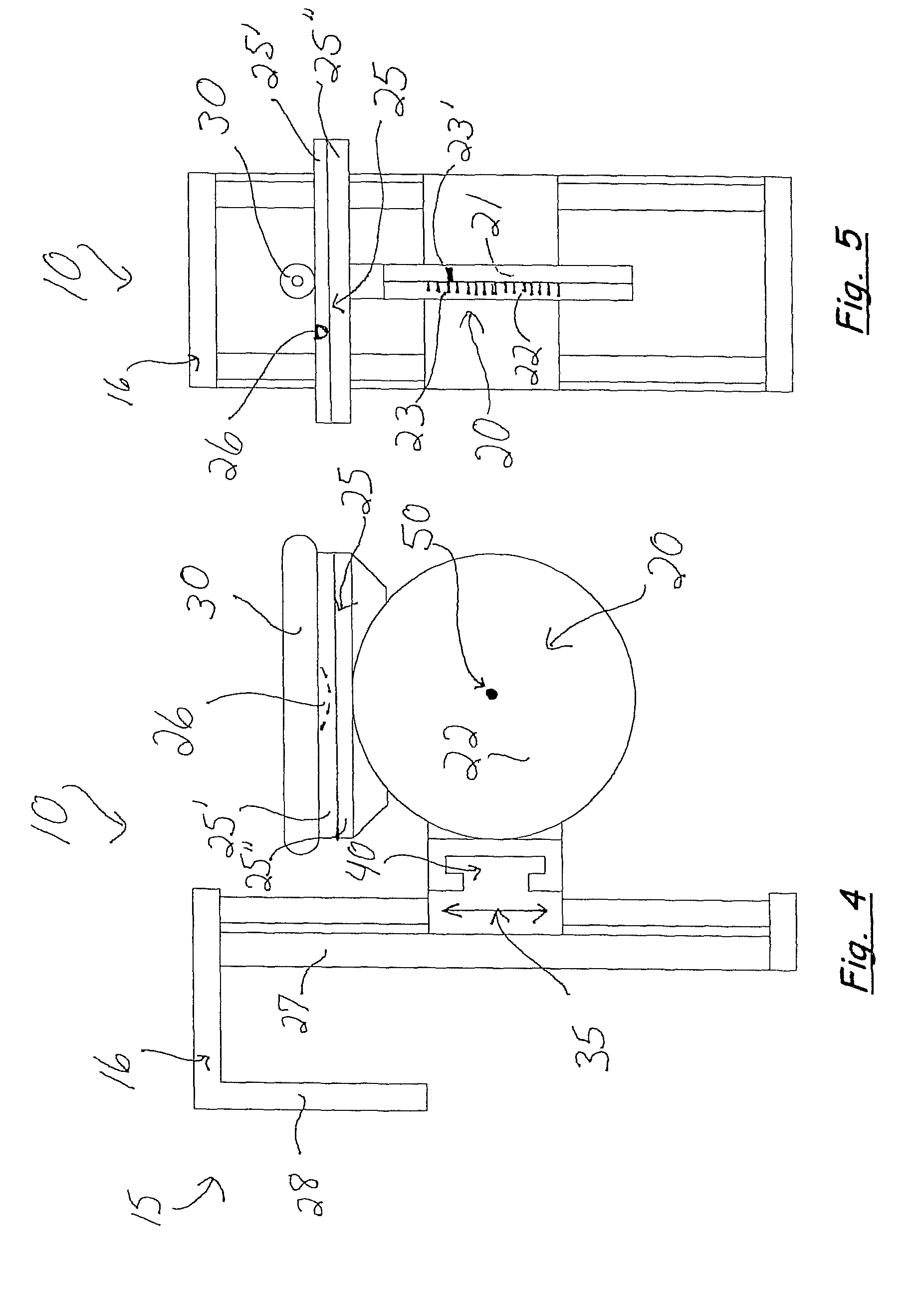
[0046]Referring to the Figures, there are shown several, but not the only, embodiments of the invented system of frame construction tools and / or methods. The invented system of tools and methods is preferably used for wood frame construction, and is therefore described in detail herein with reference to wood members, but it should be understood that the invented tools and methods may be used and / or adapted for other frame construction, such as construction using metal, polymer, concrete, or composite studs, rafters, and other members. FIGS. 1-13 schematically illustrate some but not the only embodiments of the invented tools and methods, including a laser light unit 10 and a cutting guide 210 in use in various wood frame construction applications. FIG. 14 illustrates an especially-preferred embodiment of the invented laser light unit 500, and FIGS. 15A and B, 16A and B, and 17A and B illustrate especially-preferred embodiments of cutting guides 600, 700, and 800, and FIGS. 18A and B...


PUM


Abstract

A frame construction tool system, for wood frame buildings, or for metal, polymer, concrete, or composite frame buildings, and methods of using some or all of the tools of said tool system, are particularly well-adapted for roof and/or wall construction. Preferably, a laser light unit comprises a plurality of adjustments for directing the laser light in a variety of directions, preferably for vertical, horizontal, and pivotal adjustment. The laser light unit may be used with targets, cuttings guides, and/or prism units for splitting and/or redirecting the laser beam. In one embodiment, the laser light unit is used with reflective and/or translucent/transparent targets to accurately build a “build-over roof” wherein the laser light unit maps out points and lines of an accurate connection between the roofs. In another embodiment, the laser light unit is used with one or more targets used at the top of a stud wall, to produce a straight line reference from one end/corner of a wall to another. In another embodiment, the laser light unit may be used with a cooperating cutting guide, to measure and properly cut a straight overhang for the roof or a deck and/or to measure and properly cut upending stud members in a pony wall. The preferred laser unit may be used with prism units to layout an entire building.

Description

[0001]This application claims priority of Provisional Application Ser. No. 61 / 036,073, filed Mar. 13, 2008, the entire disclosure of which is incorporated herein by this reference.BACKGROUND[0002]1. Field of the Invention[0003]The invention relates generally to tools and systems for wood frame building construction, or for other building construction that uses metal, polymer, concrete or composite members in techniques similar to traditional wood frame construction. More specifically, the invention relates to a construction system that comprises a laser light unit that may be used to accurately construct a roof, walls, and other portions of a building. The invented laser light unit may be used, preferably with invented cutting guides and / or targets and / or laser prisms, to replace construction techniques that use chalk and dry lines, rulers and squares, and other conventional tools. For example, the invented apparatus and methods may be used to accurately construct pony walls, and / or...

Claims


Application Information

Patent Timeline
Patent Type & Authority Patents(United States)
IPC IPC(8): G01C15/00G01C15/06B43L7/10
CPCG01C15/004G01C15/06Y10S33/21
Inventor TRIBBLE, RANDY LMOORE, SCOTT EWALKER, MICHAEL A
Owner TRI WALKER
Why Eureka
Try Eureka