Vent hood and flashing assembly for metal roof

a technology of metal roof and vent hood, which is applied in the field of flashing, can solve the problems of large labor intensity, large use limit, and inability to meet the needs of ventilation systems, etc., and achieve the effects of reducing labor intensity, and reducing the use of ventilation systems

Active Publication Date: 2012-07-03
RICH DANIEL L
View PDF16 Cites 50 Cited by
  • Summary
  • Abstract
  • Description
  • Claims
  • Application Information

AI Technical Summary

Benefits of technology

[0005]In order to provide a vent hood for use on a metal roof and an adequate seal therefor, my invention provides a vent hood and flashing assembly for use on an upper surface of a metal roof having an elongate projection extending upward therefrom. This assembly eliminates the previous need for extensive cutting and fitting of flashing to install a vent hood on a metal roof. The flashing includes a resilient, flexible, water-repellant sleeve that is sized to fit over, and surround, the projection. The flashing further includes a flange that extends outward from, and is attached to, a lower end portion of the flashing, which flange has an upper surface and a lower surface. A flexible, ring seal overlies the upper surface of the flange. The assembly further includes a vent hood that overlies and is joined to an upper end portion of the flashing; a cover member; a skirt that depends from the cover member; means for attaching the upper end portion of the flashing to the vent hood; and a screen that overlies the upper end portion of the flashing. The screen is dimensioned to exclude insects, rodents and other pests from entering the flashing. The skirt preferably comprises rubber, neoprene, polyurethane or similar elastomeric material.

Problems solved by technology

Such vents may include a cover or hood and a screen to prevent rain, insects and other pests from entering into the vent; see, for instance, the vent hood depicted in FIGS. 1, 2, the use of which is limited, however, to composition roofs.
If, however, one attempts to use a vent hood of the kind depicted in FIGS. 1, 2, on a metal roof, it will tend to leak because it does not conform to the irregular surface of a metal roof.
Nevertheless, prior to my invention, such a vent hood has been used even on metal roofs for lack of a better alternative, but doing so has required extensive, labor-intensive, cutting and fitting of flashing in order to create as adequate a seal as the circumstances would permit.

Method used


Image

  • Vent hood and flashing assembly for metal roof
  • Vent hood and flashing assembly for metal roof
  • Vent hood and flashing assembly for metal roof

Examples


Embodiment Construction

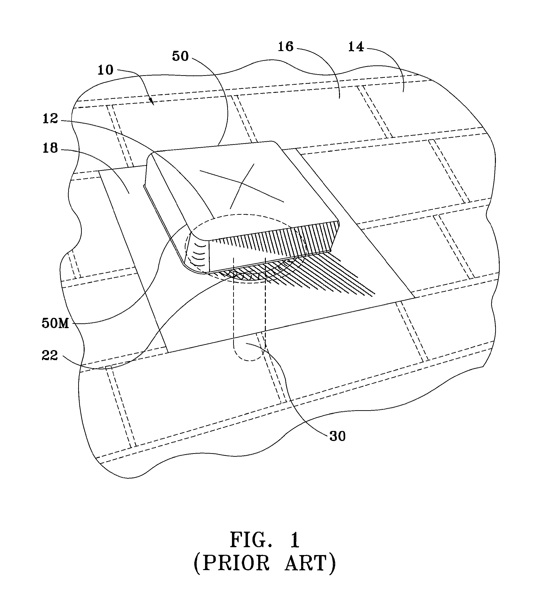
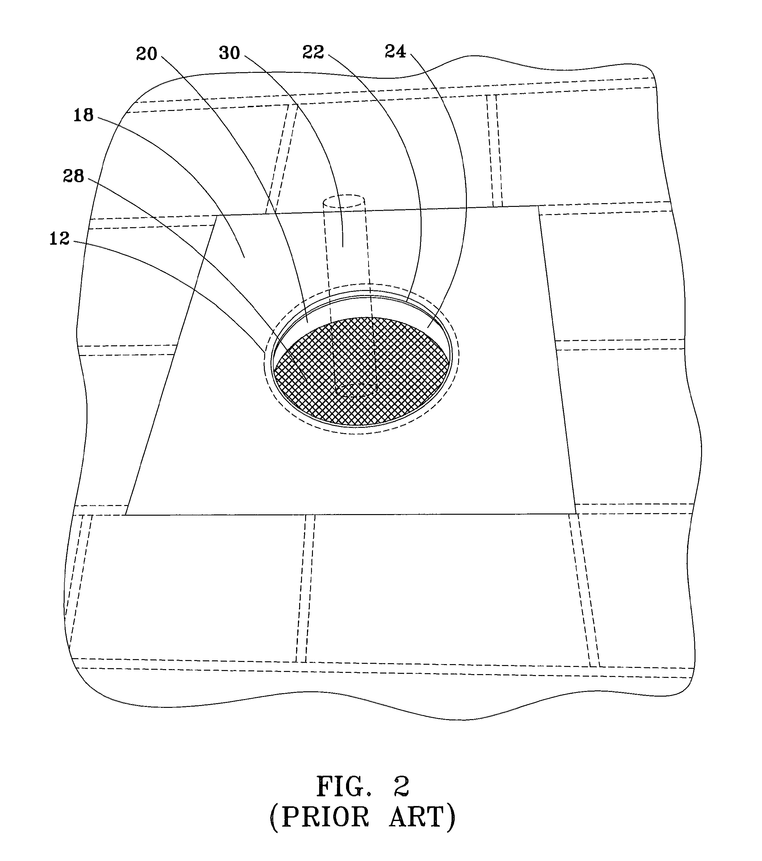
[0023]Referring to FIGS. 1 and 2, a conventional vent hood 10 is depicted installed over an opening 12 in a sloped roof 14 that is covered with asphalt shingles 16 overlying roof sheathing (not shown). A vertical, elongate projection—namely, a vent pipe 30, depicted in phantom outline—projects upward through the roof opening 12 and into interior space of the vent hood 10. The vent hood 10 includes a generally planar, sheet metal base member 18 that rests atop shingles 16 that surround the roof opening 12. The base member 18 has a circular, central opening 20 that is disposed over the roof opening 12 and is coaxially aligned, more or less, with the vent pipe 30. An upstanding lip 22 is integral with the base member 18 and defines the circular opening 20 thereof. The vent hood 10 further includes an upstanding, cylindrical collar 24 that surrounds and tightly engages an outer surface of the lip 22. An annular flange 26 extends radially outward at a circular, upper margin of the collar...


PUM


Abstract

A vent hood and flashing assembly for use on a metal roof. A vent hood overlies and is joined to flashing. A cover and a screen overlie an upper end portion of the flashing to exclude rain, snow and pests. The flashing includes a resilient, flexible, water-repellant, flexible flange that extends outward from, and is attached to, a lower end portion of the flashing and a flexible, ring seal that overlies an upper surface of the flange. The assembly can be placed over a projection through an opening in a metal roof such that the cover and screen overlie an upper end of the projection and with the flashing surrounding the projection, and the flange can be bent to sealingly conform to the roof surface and secured thereto by fasteners.

Description

BACKGROUND OF THE INVENTION[0001]1. Field of the Invention[0002]This invention relates generally to flashing used in buildings to provide a seal between a surface and a member projecting therefrom; and more specifically, this invention relates to flashing applied to seal an opening in a roof surface and to a vent that projects through an opening in said surface. Still more specifically, this invention relates to apparatus that combines a vent hood for covering a vent pipe that projects through an opening in a metal roof surface with flashing that seals said metal roof surface opening.[0003]2. General Background[0004]Various kinds of vents commonly project up through openings in the roof of a building to release indoor steam and / or other gases to the atmosphere; these include plumbing vents such as bathroom and laundry room exhaust vents, and kitchen range vents. Such vents may include a cover or hood and a screen to prevent rain, insects and other pests from entering into the vent; ...

Claims


Application Information

Patent Timeline
Patent Type & Authority Patents(United States)
IPC IPC(8): E04H12/28F23L17/02E04D13/00F24F13/08F24F7/02F23J13/08F24F13/20
CPCE04D13/1476F24F7/02F24F13/20F23J2213/204F23J13/00
Inventor RICH, DANIEL L.
Owner RICH DANIEL L
Why Eureka
Try Eureka