Light emitting device, light receiving device, data transmission system and data transmission method using the same

a technology of light emitting devices and light receiving devices, applied in electromagnetic transmission, electrical equipment, transmission, etc., can solve the problems of high encoding complexity of channel encoding techniques, and achieve the effect of low encoding complexity

Active Publication Date: 2012-07-03
IND TECH RES INST
View PDF7 Cites 65 Cited by
  • Summary
  • Abstract
  • Description
  • Claims
  • Application Information

AI Technical Summary

Problems solved by technology

However, the channel encoding technique has the high encoding complexity, needs to be combined with a lot of mathematical operations and needs to refer to the property of the channel.

Method used


Image

  • Light emitting device, light receiving device, data transmission system and data transmission method using the same
  • Light emitting device, light receiving device, data transmission system and data transmission method using the same
  • Light emitting device, light receiving device, data transmission system and data transmission method using the same

Examples


Embodiment Construction

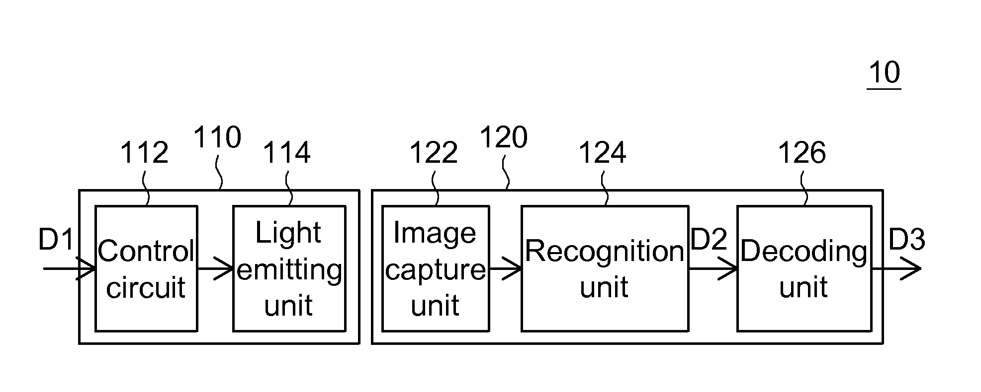
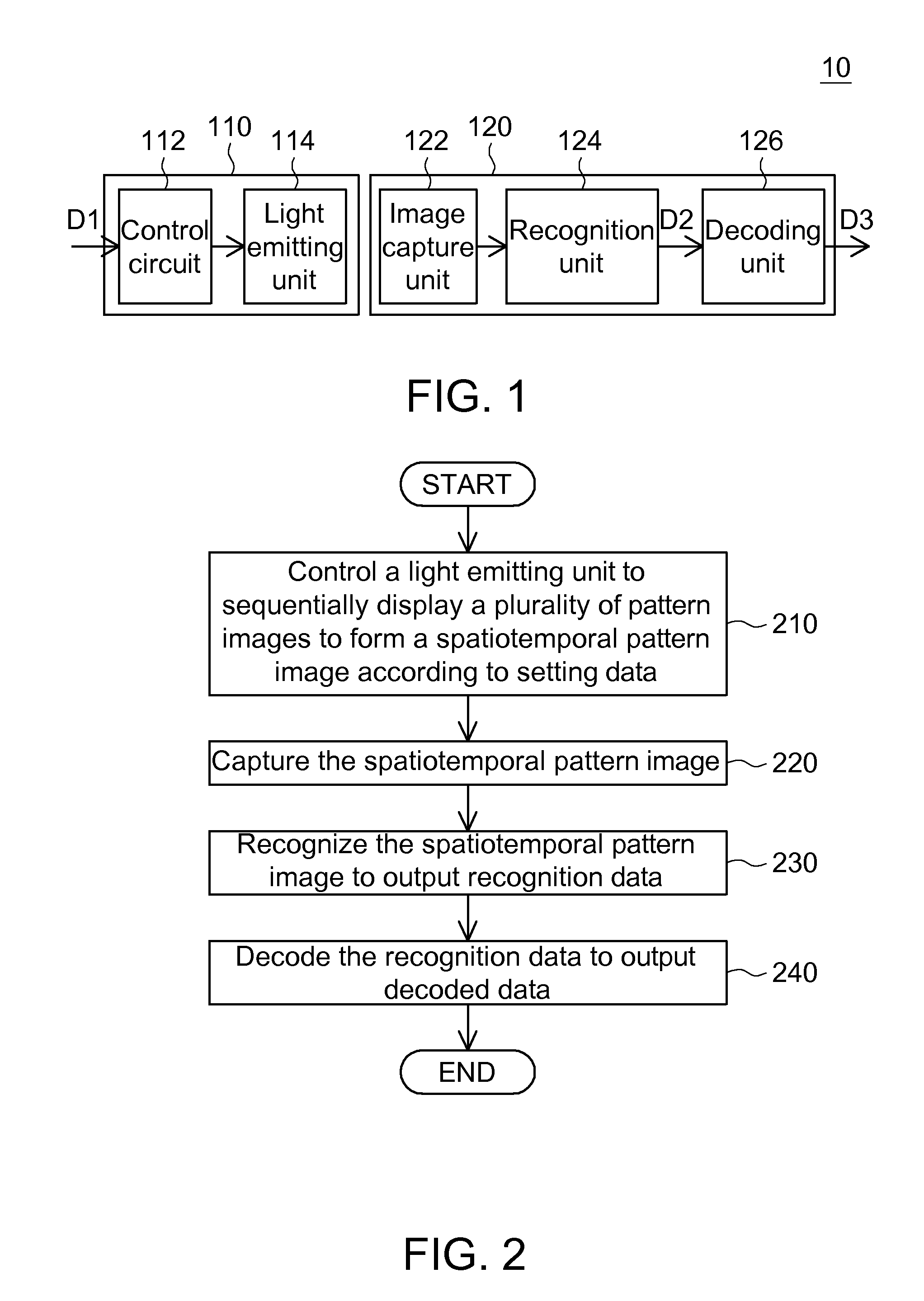
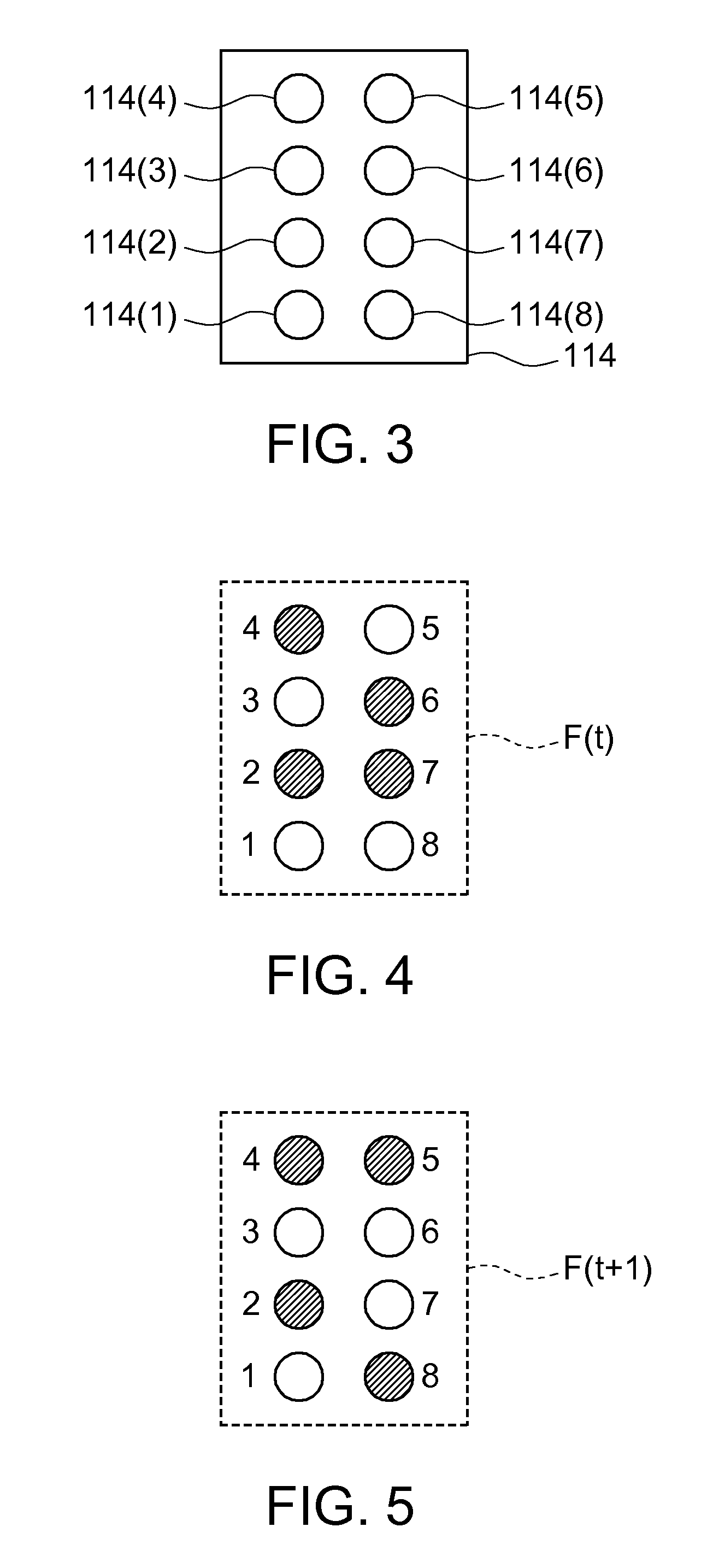
[0028]FIG. 1 is a block diagram showing a data transmission system 10 according to a preferred embodiment of the invention. FIG. 2 is a flow chart showing a data transmission method according to a preferred embodiment of the invention. FIG. 3 is a schematic illustration showing a light emitting unit. FIG. 4 shows a pattern image when a frame time is t. FIG. 5 shows a pattern image when a frame time is (t+1). FIG. 6 shows a pattern image when a frame time is (t+2). FIG. 7 shows a pattern image when a frame time is (t+3). FIG. 8 shows a pattern image when a frame time is (t+4). FIG. 9 shows a spatiotemporal pattern image.

[0029]Referring to FIGS. 1 to 9, the data transmission system 10 includes a light emitting device 110 and a light receiving device 120. The light emitting device 110 includes a control circuit 112 and a light emitting unit 114, which includes, for example, one single light emitting element or a plurality of light emitting elements. The light receiving device 120 inclu...


PUM


Abstract

A light emitting device, a light receiving device and a data transmission system and a data transmission method using the same are provided. The data transmission system includes the light emitting device and the light receiving device. The light emitting device includes a light emitting unit and a control circuit, and the light receiving device includes an image capture unit, a recognition unit and a decoding unit. The control circuit controls the light emitting unit to sequentially display a plurality of pattern images in a plurality of frame times to form a spatiotemporal pattern image according to setting data corresponding to a temporal domain and a spatial domain. The image capture unit captures the spatiotemporal pattern image. The recognition unit recognizes the spatiotemporal pattern image to output recognized data. The decoding unit decodes the recognized data to output decoded data.

Description

[0001]This application claims the benefit of Taiwan application Serial No. 98100423, filed Jan. 7, 2009, the subject matter of which is incorporated herein by reference.BACKGROUND OF THE INVENTION[0002]1. Field of the Invention[0003]The invention relates to a light emitting device, a light receiving device and a data transmission system and a data transmission method using the same.[0004]2. Description of the Related Art[0005]At present, most of the frequently seen data transmission techniques adopt the channel encoding technique to perform channel encoding on the information to be carried and then perform the transmission. The channel encoding is a special encoding method for preventing a channel effect from causing serious and remediless damages on the transmission signal. The main encoding schemes include a scrambler, a convolution encoder, an interleaving encoder, multi-level coding, pilot signals and mapping. The scrambler may generate a pseudo random bit sequence (PRBS) to be ...

Claims


Application Information

Patent Timeline
Patent Type & Authority Patents(United States)
IPC IPC(8): H04B10/00
CPCH04B10/1141
Inventor NIEN, CHIN-CHUNGKAO, CHEN-YINGHSU, CHING-TINGTIEN, I-SHINNCHEN, YI-YUAN
Owner IND TECH RES INST
Why Eureka
Try Eureka