Pedestal mounted turbocharger system for internal combustion engine

a turbocharger and internal combustion engine technology, applied in the field of turbocharger systems, can solve the problems of increasing the space required by the turbocharger in an already crowded underhood environment, increasing the noise of the known turbocharger mounting system, and increasing the space required by the turbocharger

Active Publication Date: 2012-07-10
FORD GLOBAL TECH LLC
View PDF29 Cites 6 Cited by
  • Summary
  • Abstract
  • Description
  • Claims
  • Application Information

AI Technical Summary

Benefits of technology

[0018]It is yet another advantage of the present invention that the lubricating oil and coolant supply and drain passages required for a turbocharger are routed internally within the present utility pedestal.

Problems solved by technology

Unfortunately, external fluid connections and associated pipes and hoses cause problems because hoses and fittings are known to leak and are subject to damage which may be accelerated by the high temperatures prevailing within engine compartments.
Moreover, aside from durability issues, the need for external plumbing for turbochargers increases the space required by the turbocharger in an already crowded underhood environment.
Turbochargers mounted on engines typically consume a good deal of space for another reason.
Moreover, known turbocharger mounting systems increase radiated noise because of a lack of rigidity and because of the dimensional problems associated with their usage.

Method used


Image

  • Pedestal mounted turbocharger system for internal combustion engine
  • Pedestal mounted turbocharger system for internal combustion engine
  • Pedestal mounted turbocharger system for internal combustion engine

Examples


Embodiment Construction

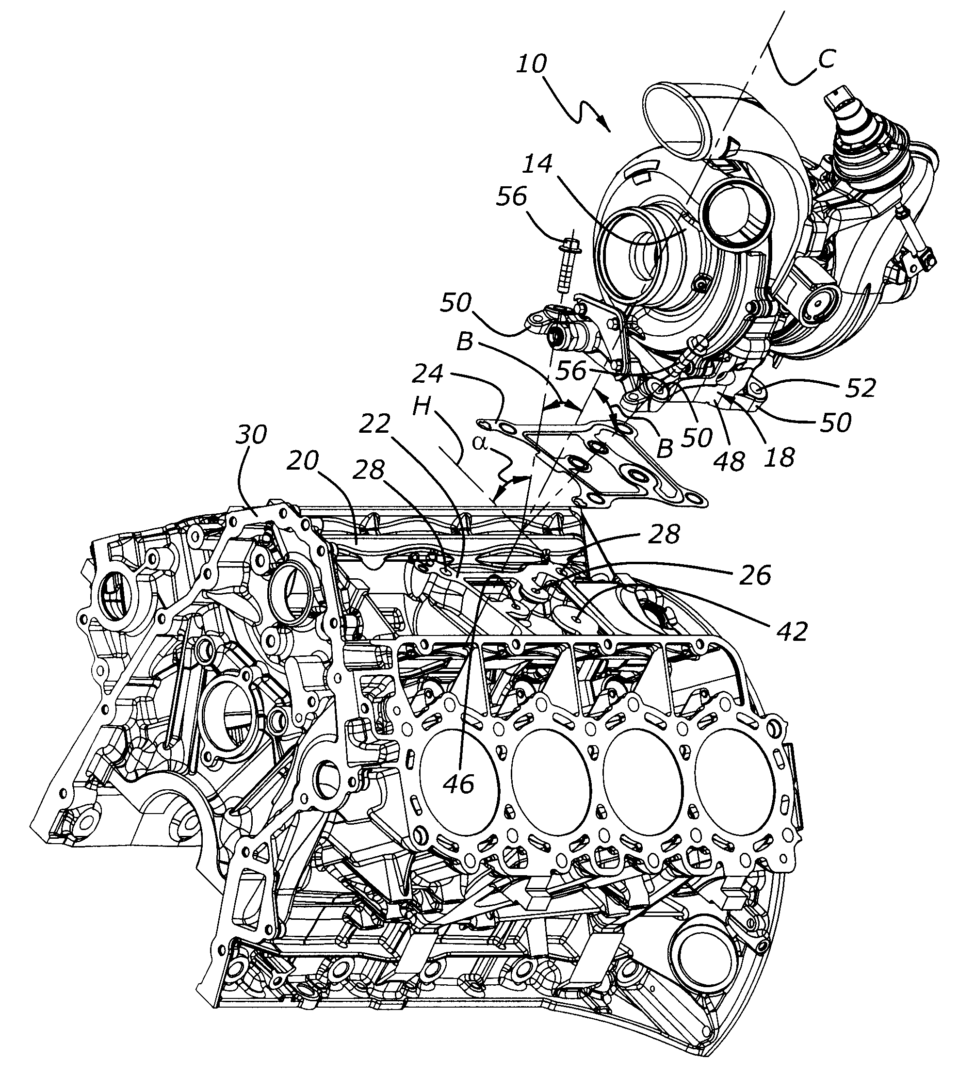
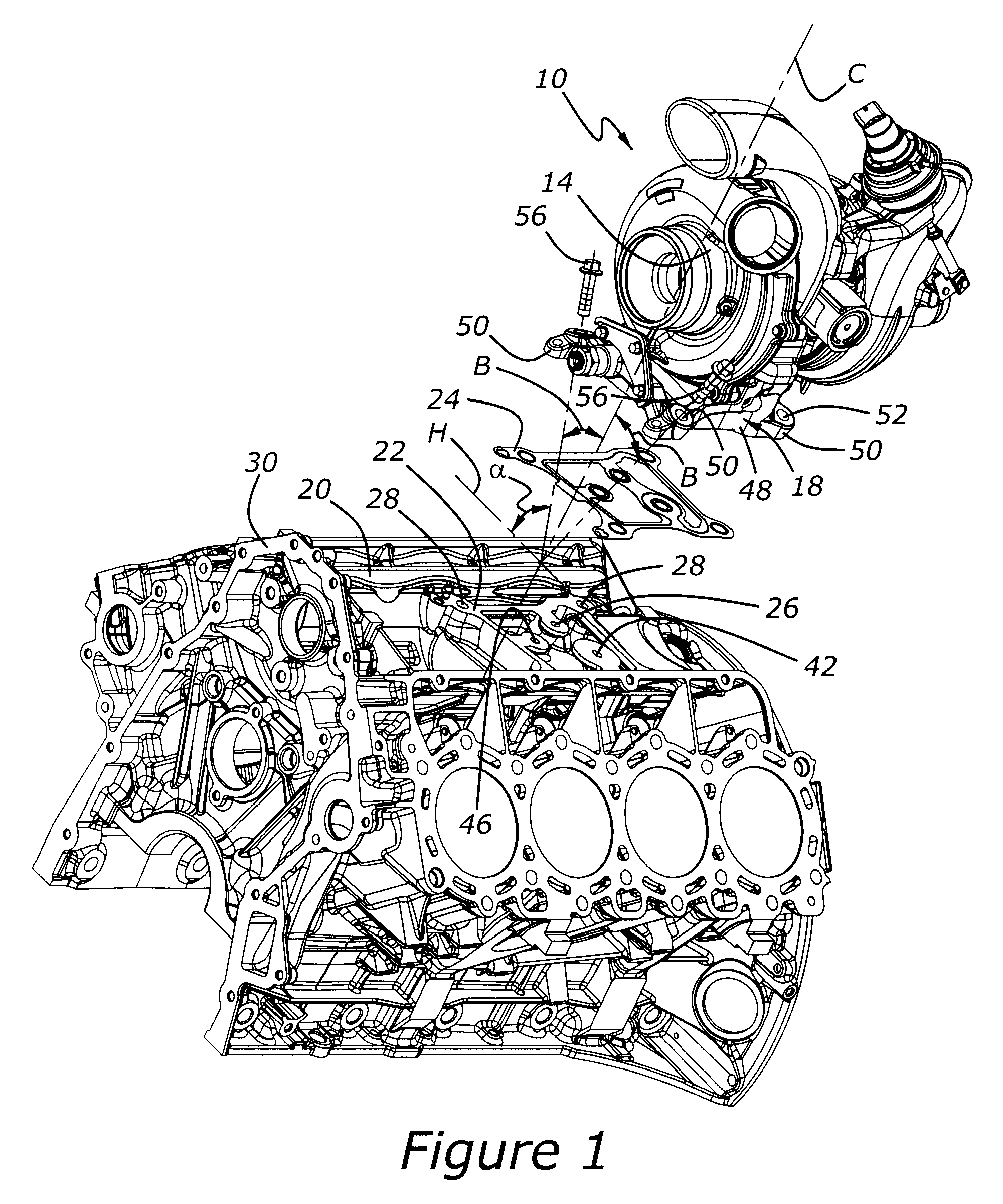
[0027]As shown in FIG. 1, turbocharger system 10 includes a turbocharger, 14, and a utility pedestal, 18. Turbocharger 14 is preferably mounted to utility pedestal 18 before turbocharger 14 is mounted upon an engine. FIG. 1 also shows an engine cylinder block, 30, having a valley, 20, into which turbocharger system 10 is placed upon a hard point, which is illustrated as generally planar mounting pad 22. Utility pedestal 18 provides rigid structural support for turbocharger 14; this helps to reduce unwanted engine noise emissions, as well as reducing unwanted vibration associated with the turbocharger. Those skilled in the art will appreciate in view of this disclosure that the term “hard point”, as used herein means either a structurally rigid mounting location such as block pad machined into the parent metal of a cylinder block, or a separate pad, such as that illustrated at 100 in FIG. 6. Mounting pad 100 is intended to be attached to an engine by bolting, or welding, or by some o...


PUM


Abstract

A turbocharger system for an internal combustion engine includes a turbocharger with a utility pedestal extending between the turbocharger and a mounting surface associated with the engine. The utility pedestal includes a mounting pad for attaching the combined turbocharger and pedestal assembly to the engine, as well as internal oil and coolant supply passages for supplying the turbocharger with coolant and lubricating oil under pressure.

Description

CROSS REFERENCE TO RELATED APPLICATIONS[0001]None.BACKGROUND OF THE INVENTION[0002]1. Field of the Invention[0003]The present invention relates to a turbocharger system including not only a turbocharger, but also a mounting pedestal configured with internal utilities needed to operate and position the turbocharger.[0004]2. Related Art[0005]Turbocharging has been used for a number of years with internal combustion engines. Although early turbochargers were often cooled primarily by air, as well as by the flow of oil through the turbocharger's bearings, later model turbochargers, especially larger turbochargers and those installed in heavy duty engines, generally utilize coolant circulating from the engine's cooling system through the turbo, and then back to the engine's main cooling system. Of course, turbochargers also require an oil supply and drain utilities to lubricate the bearings associated with the turbocharger. Needless to say, the provision of a source of coolant and a sour...

Claims


Application Information

Patent Timeline
Patent Type & Authority Patents(United States)
IPC IPC(8): F02G3/00F02B33/44
CPCF01M11/02F02B39/005F02B39/14F01M2011/021F01P2060/12F02B75/22F02B2720/252
Inventor HUDSON, ANTHONY WILLIAMSEXTON, PATRICKPALAZZOLO, CHRISTOPHER KELLYCOWLAND, CHRISTOPHER
Owner FORD GLOBAL TECH LLC
Why Eureka
Try Eureka