Model railroad assembly

a technology of model railroads and parts, applied in the field of model trains and railroads, can solve the problems of insufficient track switches and/or insufficient track lengths of model railroads, and achieve the effect of facilitating switch clearan

Inactive Publication Date: 2012-07-10
SCHLUETER WAYNE +1
View PDF12 Cites 1 Cited by
  • Summary
  • Abstract
  • Description
  • Claims
  • Application Information

AI Technical Summary

Benefits of technology

[0011]The instant inventive model railroad assembly preferably further comprises a support leg having proximal and distal ends, and second mounting means, the second mounting means being adapted for fixedly attaching the support leg's proximal end to the arm's distal end. In the preferred embodiment, the second mounting means are further adapted for pivotally moving the support leg between third and fourth positions, the support leg's distal end, upon movement of the arm to the first position and upon movement of the leg to the third position, extending downwardly for providing vertical support at the distal end of the arm. Upon retracting pivoting movement of the support leg to the fourth position, the support leg preferably co-extends with and directly underlies the arm for compact and unobtrusive leg storage.
[0012]In use of the instant inventive model railroad assembly, an operator may move the arm to the first position, and may thereby cause the assembly's electrical connecting means to extend the provided DC power of the first track matrix to the second track matrix. Where a support leg is provided, the support leg may be pivoted downwardly for vertical support and horizontal positioning of the arm. Thereafter, a first model railroad train may be rollably moved from the first track matrix onto the second track matrix, allowing the position of such first train to allow clear passage for various movements of other model railroad trains upon the first track matrix, or allowing the first model railroad train to reverse its direction of travel, or facilitating switch clearance. Upon termination of model railroad train supporting use of the arm component, the preferably provided support leg may be pivoted to the fourth compact storage position, and the arm may be compactly pivoted downwardly to the second position. Alternatively, the arm's second position may comprise one in which the arm is wholly removed and is separately stored. Regardless of which arm storing second position is utilized, the electrical connecting means are preferably adapted to terminate the supply of electrical power upon movement of the arm toward the second position.

Problems solved by technology

In many situations, a model railroad's track matrix has insufficient track lengths and / or insufficient track switches to facilitate such functions.

Method used


Image

  • Model railroad assembly
  • Model railroad assembly
  • Model railroad assembly

Examples


Embodiment Construction

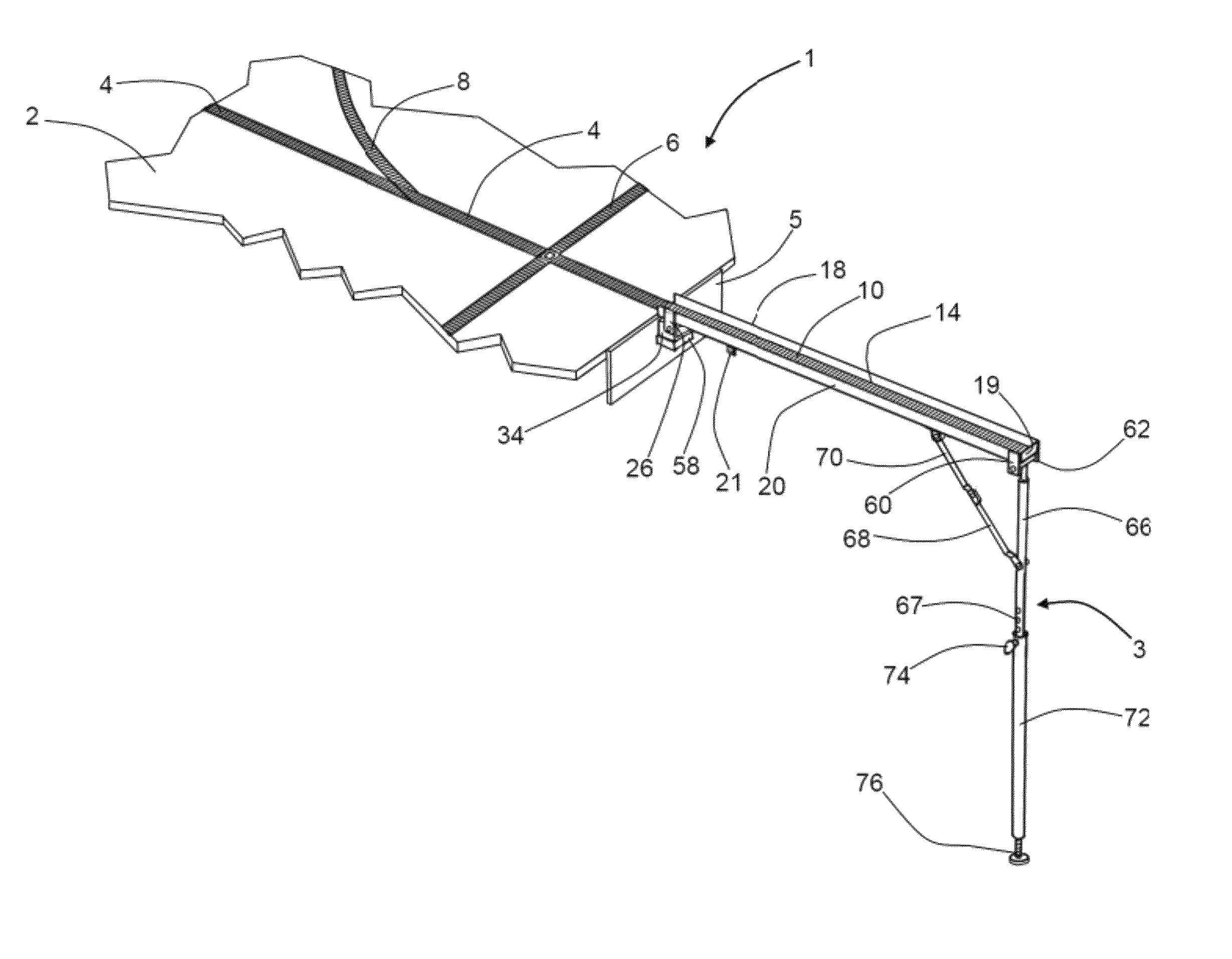
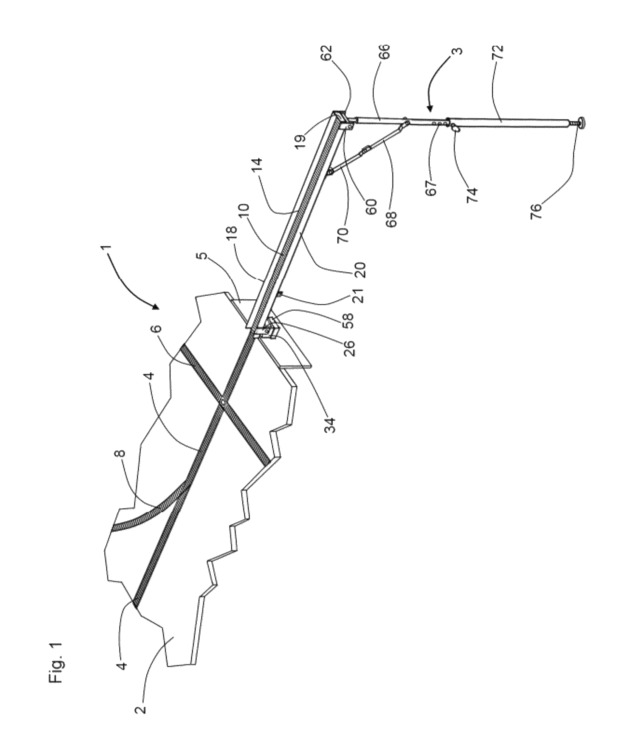
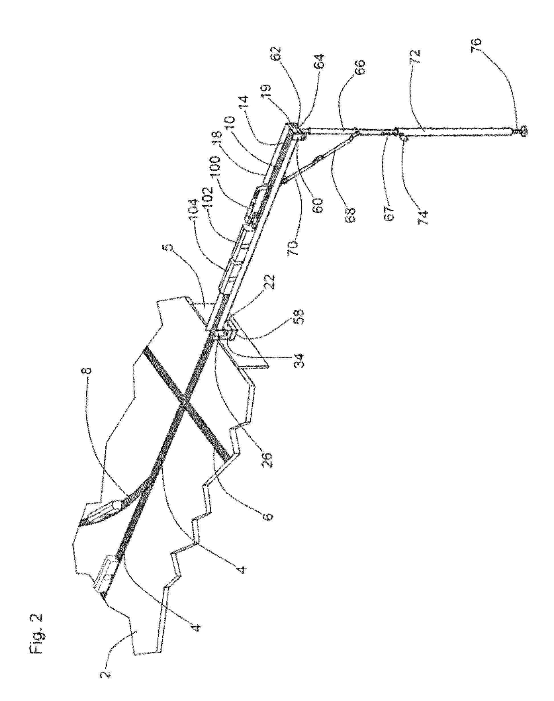
[0021]Referring now to the drawings, and in particular to FIGS. 1 and 5, a preferred embodiment of the instant inventive model railroad assembly is referred to generally by Reference Arrow 1. The assembly 1 preferably comprises a table 2 and an arm 18,20,22 which is configured as an upwardly opening “C” channel beam. In the preferred embodiment, the web portion 22 of the “C” channel beam serves as an extension of table 2, while such beam's lateral flanges 18 and 20 advantageously function as side rails for prevention of falling of model railroad engines and cars. A barrier or end wall 19 preferably spans laterally between the distal ends of flanges 18 and 20 to prevent trains from rolling distally off of the arm 18,20,22.

[0022]Referring to FIG. 1, the assembly 1 preferably further comprises a first track matrix 4,6,8 which is fixedly attached to the upper surface of table 2. Referring further to FIG. 5, a second track matrix 10 is similarly fixedly attached to and is support upon th...


PUM


Abstract

A model railroad assembly incorporating a table, an arm having proximal and distal ends, first and second track matrices, the first and second track matrices having electrically positive rails and electrically negative rails, the first track matrix being positioned upon the upper surface of the table, and the second track matrix being positioned upon the arm's upper surface; a hinge connector operatively attaching the arm to the table, the hinge connector facilitating movement of the arm between first and second positions; and a plurality of pivoting electric switch contacts adapted for electrifying the second track matrix upon movement of the arm to the first position, and for de-electrifying the second track matrix upon movement of the arm toward the second position.

Description

FIELD OF THE INVENTION[0001]This invention relates to model trains and railroads. More particularly, this invention relates to track adaptations of model railroads for facilitation of model railcar and model engine passage, for facilitation of switch clearance, and for facilitation of model railcar and model engine travel direction reversal.BACKGROUND OF THE INVENTION[0002]Recreational and hobby model train assemblies commonly include a matrix of O, S, HO, or N gauge track which rests upon and is fixedly attached to the upper surface of a display table. The metal rails of such track matrix are typically powered by an induced electrical potential difference wherein one of the rails is electrically positive, and wherein the other of the rail is relatively electrically negative. The rails' electrical potential difference in turn powers a DC electric motor within train's engine, driving the train. Engines and cars traveling upon such track matrix desirably have a capability of passing o...

Claims


Application Information

Patent Timeline
Patent Type & Authority Patents(United States)
IPC IPC(8): E01B23/00
CPCA63H19/24
Inventor SCHLEUTER, WAYNE
Owner SCHLUETER WAYNE
Why Eureka
Try Eureka