Parachute with one-way valve device

a technology of one-way valve and parachute, which is applied in the field of parachutes and paragliders, can solve the problems of loss of parachute rigidity, and further shrinkage in size, so as to reduce stall speed, increase performance characteristics, and increase canopy area

Inactive Publication Date: 2012-07-10
MULLINS CHARLES MICHAEL
View PDF11 Cites 7 Cited by
  • Summary
  • Abstract
  • Description
  • Claims
  • Application Information

AI Technical Summary

Benefits of technology

[0008]The invention disclosed herein maintains the rigidity and shape of a ram-air parachute when air pressure against the air inlets of the parachute provides inadequate pressurization. Generally this is accomplished by closing off the air inlets on one or more cells and turning one or more of the crossports into one-way valves. Valving can be accomplished by partially sewing a panel of material, such as zero-porosity or low-porosity parachute material, over the crossport. When pressure is lower on the side of the crossport where the valve panel is attached, air is allowed to flow through the crossport to pressurize that cell and any other cells in communication with that cell. However when air pressure is higher in the cell on the side of the crossport where the valve panel is attached than the other side of the crossport, the airflow is reversed and the valve panel is urged against the rib material surrounding the crossport creating a seal preventing depressurization of the parachute.
[0009]Partial attachment of the valve panel to the rib material prevents the valve from being forced through the crossport. In another embodiment the valved crossports possess a breathable mesh material attached over the opening of the crossports. In such embodiment the mesh material prevents the valve material from passing through the crossport. By positioning the valved crossports within the ribs of the parachute, an airlock designed parachute can be achieved that also possess the additional stabilizing effects of cross bracing.
[0010]The resulting parachute provides reduced stall speeds at slow speeds. Slower stall speeds allow the user to select a smaller parachute for increased performance characteristics while providing a larger canopy area at landing than what could be achieved with a parachute otherwise lacking one-way valves. The resulting parachute also increases stability in turbulent or low speed conditions, increasing the user's safety and generally providing for a more enjoyable experience.

Problems solved by technology

Loss of parachute rigidity occurs when the parachute is slowed for landing and can also occur when flying in turbulent air.
When the parachute is slowed for landing, however, the parachute looses rigidity and shrinks further in size, reducing lift and increasing the stall speed of the parachute.
Reduced stall speed during slow landings due to loss of rigidity and shrinkage is one problem associated with ram air inflated parachutes.
Loss of rigidity may ultimately lead, however, to the parachute canopy collapsing which can lead to injury or death of the user.
Should the canopy be allowed to lose sufficient rigidity, the parachute may collapse and greatly increase the vertical descent of the operator.
Landing is a particular vulnerable time for the parachute user, where slow speed, ground induced turbulence and reduced recovery time increase the risk of canopy collapse.

Method used


Image

  • Parachute with one-way valve device
  • Parachute with one-way valve device
  • Parachute with one-way valve device

Examples


Embodiment Construction

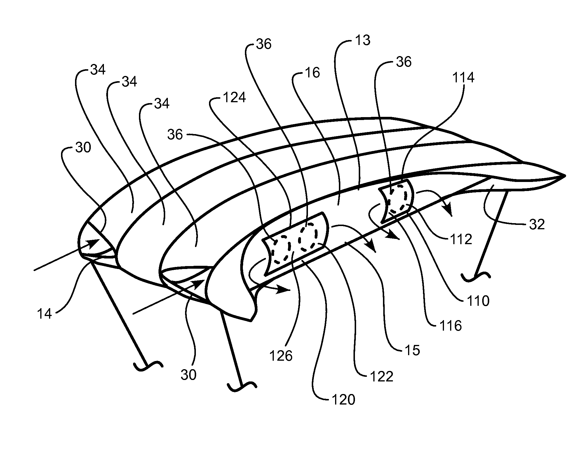
[0025]The drawings illustrate an invention that enables a parachute to retain its rigidity and shape when flying in turbulent air or at low speeds.

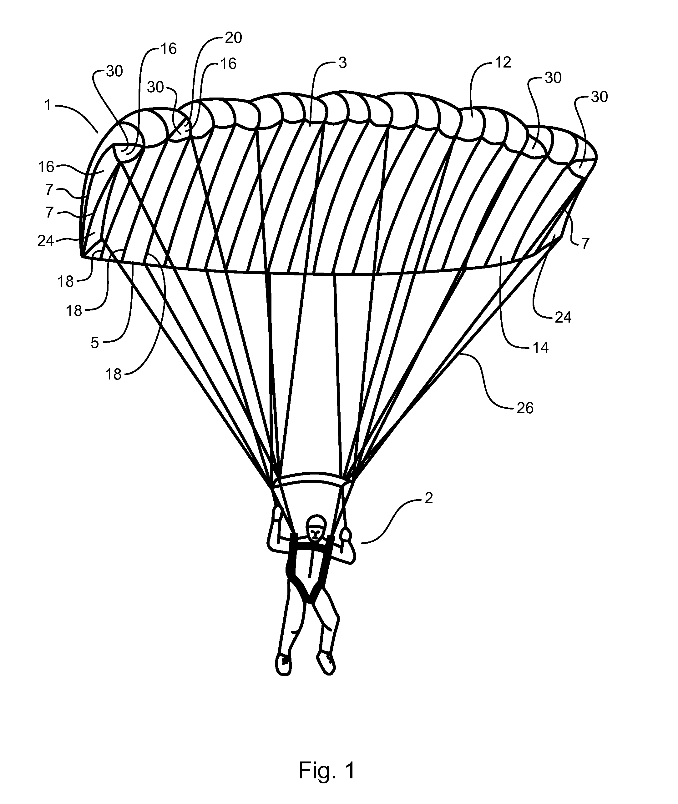
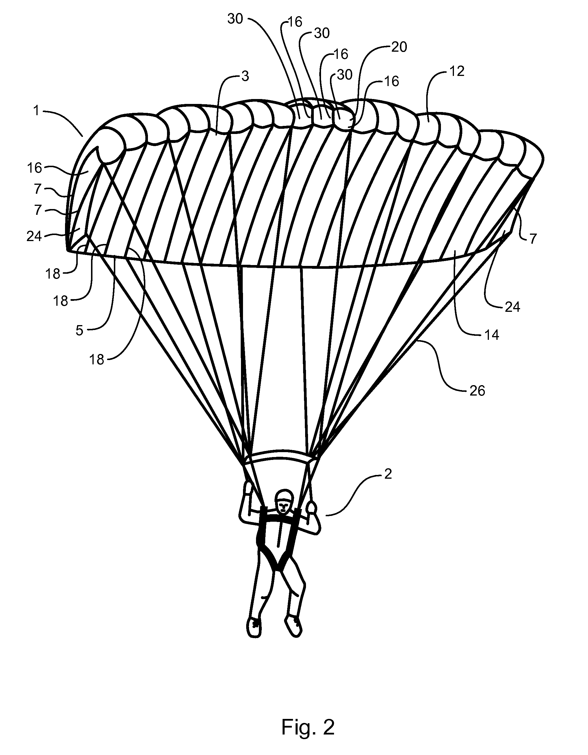
[0026]FIG. 1 shows one embodiment of the present invention 1 employed as a parachute and deployed and inflated in flight. The parachute 1 is comprised of a an upper skin 12 of a generally rectangular shape and a lower skin 14 of substantially the same configuration each having a leading edge 3 a trailing edge 5 and a pair of generally opposing lateral edges 7. The lower skin 14 is disposed beneath and joined to the upper skin 12 at the trailing edge 5, the leading edge 3 and by a plurality of elongated rib members 16. The joining of the rib members 16 in the present embodiment can be seen in FIG. 1 as parallel seam lines 18. Load bearing ribs 20 bear and distribute the weight of the payload such as an operator 2, suspended beneath the parachute 1. Generally, suspension lines 26 connect to, or proximately to a load bearing rib 20 that in t...


PUM


Abstract

A multi-celled ram-air parachute possessing one or more internal one-way valved air passages between at least two parachute cells to maintain positive air pressure within the parachute for the purpose of maintaining shape and rigidity when less than optimal airspeed is present thereby increasing a user's control and safety.

Description

BACKGROUND OF THE INVENTION[0001]This invention relates generally to parachutes and paragliders. More particularly, it relates to ram-air type parachutes and paragliders that include a plurality of cells with at least one valve in at least one of the cells to inhibit deformation of the air wing structure.[0002]Much like an airplane wing, a ram-air parachute possesses an airfoil that provides lift and allows the operator to control the direction, speed and rate of descent. The shape and rigidity of a parachute determine such flight characteristics. Generally, a ram-air parachute consists of an upper surface and a lower surface connected by a plurality of vertically attached ribs. A cell of the parachute is the part of the parachute between the upper and lower skins bordered by a rib on one side and an adjacent rib on the other. Much like an airplane wing, one of the purposes of these ribs is to help the wing to keep its shape and strength. Load bearing ribs support and distribute the...

Claims


Application Information

Patent Timeline
Patent Type & Authority Patents(United States)
IPC IPC(8): B64D17/00
CPCB64D17/025
Inventor MULLINS, CHARLES MICHAEL
Owner MULLINS CHARLES MICHAEL
Why Eureka
Try Eureka