
Shock-absorber assembly and corresponding motor vehicle

a technology for shock absorption and motor vehicles, which is applied in the direction of vehicle bodies, superstructure subunits, and monocoque constructions. it can solve the problems of lateral beams being ripped from the body of the vehicle, transverse beams coming into contact with the radiator, and damag

Inactive Publication Date: 2012-07-10
FAURECIA BLOC AVANT
View PDF16 Cites 11 Cited by
  • Summary
  • Abstract
  • Description
  • Claims
  • Application Information

AI Technical Summary

Benefits of technology

[0007]To this end, the invention relates to a front shock-absorber assembly for a motor vehicle comprising, at each of the right-hand and left-hand sides thereof, at least a lower longitudinal structural element and an upper longitudinal structural element. The shock-absorber assembly comprises a high-energy impact-absorbing structure which comprises an elongate right-hand an...

Problems solved by technology

However, it does not allow the cohesion of the body to be maintained during an axial impact at high speed between vehicles which have different gauges and / or during a corner impact.
Consequently, the lateral beams are torn from the body of the vehicle.
Furthermore, since a radiator is located behind the transverse beams, when the deformable elements are crushed along the thickness thereof, the transverse beams come into contact with the radiator and damage it.

Method used


Image

  • Shock-absorber assembly and corresponding motor vehicle
  • Shock-absorber assembly and corresponding motor vehicle
  • Shock-absorber assembly and corresponding motor vehicle

Examples


Embodiment Construction

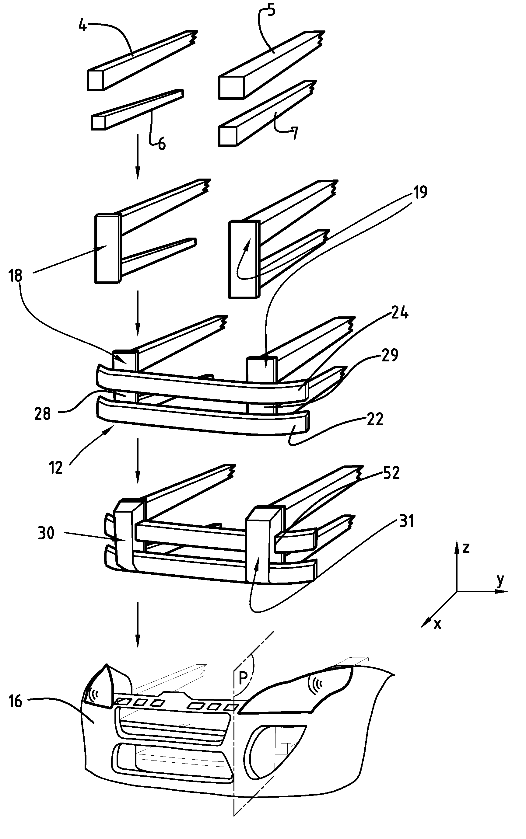
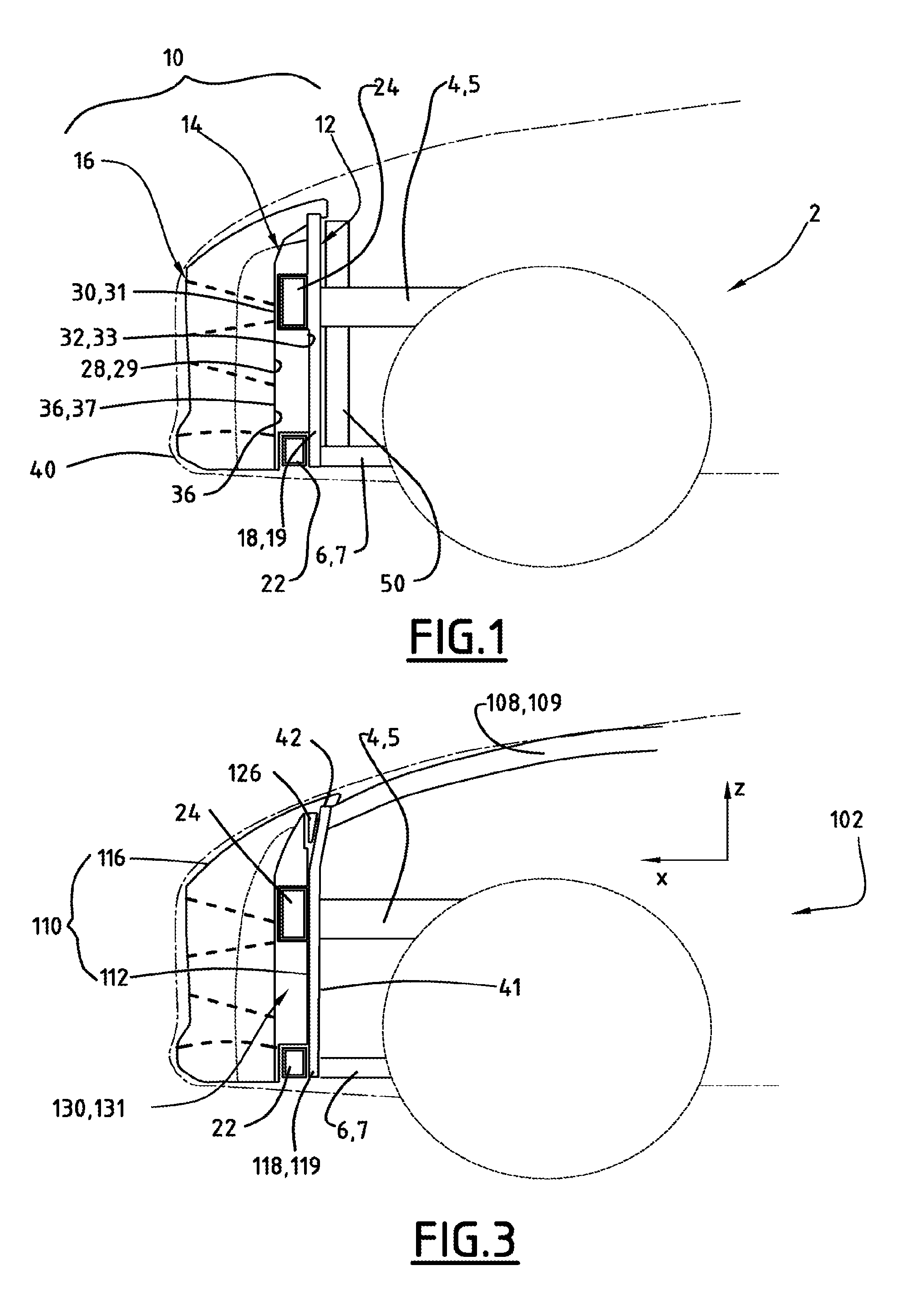
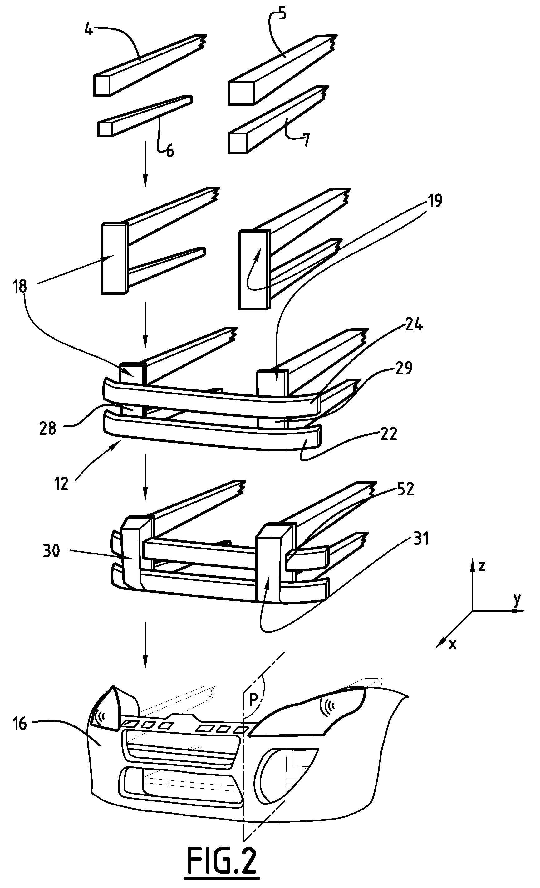
[0023]With reference to FIG. 1, a front face of a motor vehicle 2 comprises, in the upper portion thereof, a right-hand side sill 4 and a left-hand side sill 5 and, in the lower portion thereof, a right-hand cradle extension 6 and a left-hand cradle extension 7.

[0024]The shock-absorber element 10 with which the front face of the vehicle 2 is provided is fixedly joined to the side sills 4 and 5 and the cradle extensions 6 and 7. The shock-absorber element 10 comprises, successively from the rear to the front along the longitudinal axis X of the vehicle 2, a high-energy impact-absorption structure 12, an intermediate-energy impact absorption means 14, and a low-energy impact absorption framework 16.

[0025]The high-energy impact absorption structure 12 comprises two plates, a right-hand plate 18 and a left-hand plate 19. The right-hand plate 18 is rigid and is, for example, constituted by a metal plate of aluminium or steel having a substantially rectangular shape. The right-hand plate ...


PUM


Abstract

A front shock-absorber assembly for a motor vehicle includes, at each of the right-hand and left-hand sides thereof, at least a lower longitudinal structural element (6, 7) and an upper longitudinal structural element (4, 5). The shock-absorber assembly includes a high-energy impact absorption structure (12) which includes an elongate right-hand plate (18) and left-hand plate (19), each plate being fixedly joined to a lower longitudinal element and an upper longitudinal element located at the same side of the vehicle; and a deformable right-hand element (30) and left-hand element (31) for absorbing medium-energy impacts, a rear surface of a deformable element moving into abutment against the majority of a front surface of an associated plate.

Description

BACKGROUND OF THE INVENTION[0001]The present invention relates to a shock-absorber assembly for a motor vehicle comprising, at each of the right-hand and left-hand sides thereof, at least a cradle extension end and a side sill end.[0002]Such a shock-absorber assembly is known, for example, from document US 2005 / 0046226 A1. The shock-absorber assembly comprises a lower transverse beam which connects the ends of the cradle extensions and an upper transverse beam which connects the ends of the extensions of the side sills. Furthermore, the shock-absorber assembly comprises a deformable energy absorption element which is interposed between the two rigid structures which are, on the one hand, the beam and, on the other hand, a cradle extension or a side sill.[0003]Motor vehicles must comply with various standards relating to impacts. The shock-absorber must be capable of absorbing the significant level of energy released during an impact at high speed (64 km / h) in order to protect the oc...

Claims


Application Information

Patent Timeline
IPC IPC(8): B60R19/02
CPCB60R19/12B62D25/084B60R19/26B60R2019/186
Inventor GONIN, VINCENT
Owner FAURECIA BLOC AVANT
Learn More