
Measuring agglutination parameters

a technology of agglutination parameters and measurement methods, applied in the field of measuring agglutination parameters, can solve the problems of prior tagging techniques, optical methods that are not suitable for use with raw samples, and quantitative tests based on optical detection of large particles are only moderately sensitive, so as to alleviate one or more, the effect of eliminating one or mor

Active Publication Date: 2012-07-10
KONINK PHILIPS ELECTRONICS NV
View PDF10 Cites 4 Cited by
  • Summary
  • Abstract
  • Description
  • Claims
  • Application Information

AI Technical Summary

Benefits of technology

[0013]It is an object of the present invention to provide good methods and systems for measuring agglutination parameters. It is an advantage of embodiments according to the present invention that these mitigate, alleviate or eliminate one or more of the above mentioned disadvantages of the prior art singly or in any combination. The above objective is accomplished by a method and device according to the present invention.
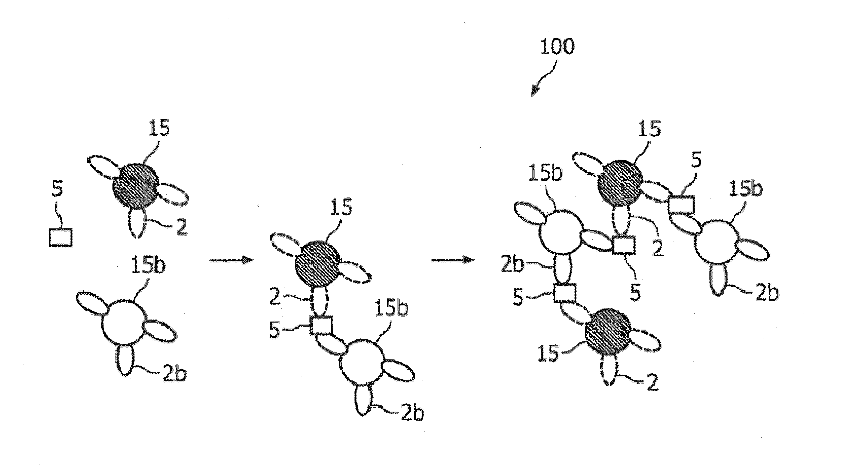
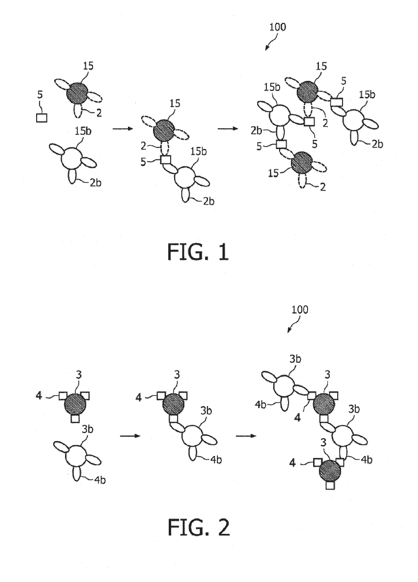
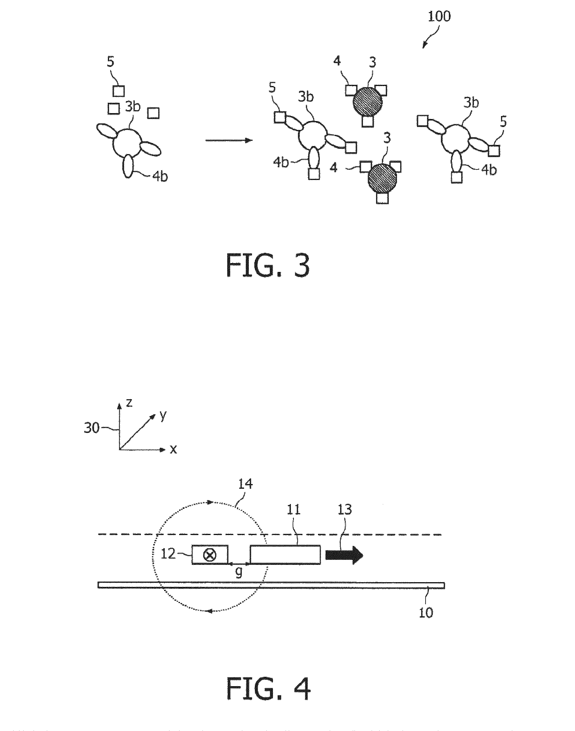
[0014]The present invention provides a method for measuring agglutination of one or more particles in a target-induced agglutination assay performed in a reaction chamber, the method comprising the steps of providing magnetic particles in an assay, said magnetic particles being capable of binding to a target, performing an agglutination process resulting in agglutinated particles, the agglutinated particles comprising a least one of said magnetic particles. The method further comprises applying an alternating current magnetic field (HAC) to the assay in the reaction chamber, and measuring with said at least one sensor element, an effect of the HAC on the one or more magnetic particles unattached to any surface of the reaction chamber, wherein the measured effect is indicative of one or more agglutination parameters. It is an advantage of embodiments according to the present invention that a high throughput can be obtained. It is an advantage of embodiments according to the present invention that a high sensitivity can be obtained. It is an advantage of embodiments according to the present invention that non-specific formation of clusters can be minimized. The assay, or the reaction chamber wherein the assay may be kept may be in the vicinity of the sensor element. The magnetic particles can be detected directly by the sensing method, or the particles can be further processed prior to detection. An example of further processing is that materials are added or that the (bio) chemical or physical properties of the particle are modified to facilitate detection.

Problems solved by technology

Quantitative tests based on optical detection of large particles are only moderately sensitive because they rely on measurements of turbidity (transmitted light through sample) or nephelometry (scattered light through sample), both of which are influenced by background interference from particulate matter.
Consequently, optical methods are not suitable for use with raw samples such as whole blood, which contains cells, and saliva, which may have food particles.
However, these prior tagging techniques have various well-known disadvantages.
However, SQUIDs are quite sensitive measurement devices, but suffer inter alia from the disadvantage that the devices have to be cooled around cryogenic temperatures.
However, working in the kilo-Hertz regime of oscillation may introduce unnecessary noise contributions, and additionally the application of a moving, in particular rotating, sample holder complicates the design as the rotating sample holder has to be relatively precise when the rotation is applied for decoupling of measurement and excitation.
Additionally, the rotating sample holder does not easily facilitate sample manipulation immediately prior to, during, or immediately after magnetic measurement.
Moreover, the coil technology applied by Simmonds et al. is not very sensitive, and thus relatively large amount of magnetic material is required for detection, which therefore increases the need for higher sample volumes.
Finally, Simmonds et al. only measures the total amount of magnetic material both in the form of clusters and single particles, and effectively they do not distinguish between the two forms making it impossible to measure agglutination parameters.
For example, it is a challenge in agglutination assays to detect a low number of clustered species in a background of many un-clustered species, and / or to detect a low number of un-clustered species in a background of many clustered species.

Method used


Image

  • Measuring agglutination parameters
  • Measuring agglutination parameters
  • Measuring agglutination parameters

Examples


Embodiment Construction

[0062]The present invention will be described with respect to particular embodiments and with reference to certain drawings but the invention is not limited thereto but only by the claims. Any reference signs in the claims shall not be construed as limiting the scope. The drawings described are only schematic and are non-limiting. In the drawings, the size of some of the elements may be exaggerated and not drawn on scale for illustrative purposes.

[0063]Where the term “comprising” is used in the present description and claims, it does not exclude other elements or steps. Where an indefinite or definite article is used when referring to a singular noun e.g. “a” or “an”, “the”, this includes a plural of that noun unless something else is specifically stated.

[0064]Furthermore, the terms first, second, third and the like in the description and in the claims, are used for distinguishing between similar elements and not necessarily for describing a sequence, either temporally, spatially, i...


PUM

PropertyMeasurementUnit
angleaaaaaaaaaa
angleaaaaaaaaaa
angleaaaaaaaaaa

Abstract

A method and system for measuring agglutination in a target-induced agglutination assay with one or more magnetic particles is performed in a reaction chamber. After the magnetic particles, which are capable of binding to a target are provided in the assay, an agglutination process is performed resulting in agglutinated particles. Further an alternating current magnetic field (HAC) is applied to the assay. The method further includes measuring an effect of the HAC on the one or more magnetic particles unattached to any surface. The measured effect is indicative of one or more agglutination parameters.

Description

FIELD OF THE INVENTION[0001]The present invention relates to the field of biological, chemical or biochemical sensing. More particularly, the present invention relates to a method for quantitatively measuring one or more agglutination parameters of magnetic labels in a target-induced agglutination assay. The invention also relates to a corresponding kit, and a corresponding device.BACKGROUND OF THE INVENTION[0002]Recent efforts have been given to measurement techniques for determining the presence, and possibly the level of concentration, of targets in a larger mixture or solution in which the particles reside. It is often desirable to measure relatively low concentrations of certain organic compounds. In medicine, for example, it is very useful to determine the concentration of a given kind of molecule, usually in solution, which either exists naturally in physiological fluids e.g. blood or urine or which is introduced into the living system e.g. drugs.[0003]One broad approach used...

Claims


Application Information

Patent Timeline
Patent Type & Authority Patents(United States)
IPC IPC(8): G01R33/00G01N33/553
CPCB82Y25/00G01N15/0266G01N27/745G01N33/54333G01R33/093G01R33/1269G01N2015/0092Y10S436/806
Inventor DITTMER, WENDY UYENDE KIEVIT, PEGGYNIEUWENHUIS, JEROEN HANSPRINS, MENNO WILLEM JOSEVAN IJZENDOORN, LEONARDUS JOSEPHUSJANSSEN, XANDER JOZEF ANTOINE
Owner KONINK PHILIPS ELECTRONICS NV
Learn More