Exposing pixel groups in producing digital images

a digital image and pixel group technology, applied in the field of two-dimensional image sensor array image capture device, can solve the problems of insufficient light, noisy image production, and inability to obtain such high-quality image sequences, and achieve the effects of increasing spatial resolution, temporal resolution and image quality

Active Publication Date: 2012-07-10
OMNIVISION TECH INC
View PDF31 Cites 17 Cited by
  • Summary
  • Abstract
  • Description
  • Claims
  • Application Information

AI Technical Summary

Benefits of technology

[0023]An advantage of the present invention is that sequences of color images with increased spatial resolution, temporal resolution and image quality can be produced without the need for additional lenses and image sensor arrays.
[0024]A further advantage of the present invention is that sequences of color images with increased spatial resolution, temporal resolution and image quality can be produced without the need for computationally complex and memory intensive algorithms.
[0025]A further advantage of the present invention is that combinations of sequences of low spatial resolution, high temporal resolution, color images and sequences of high spatial resolution, low temporal resolution, color images can be produced without the need for additional lenses and image sensor arrays.
[0026]A further advantage of the present invention is that the extended dynamic range image can be produced without the need for additional lenses and image sensor arrays.
[0027]A further advantage of the present invention is that the extended dynamic range image can be produced with lower buffering and without the need for computationally complex and memory intensive algorithms.

Problems solved by technology

With many current image sequence capture devices, however, it is not possible to obtain such high quality image sequences.
In a low-light environment, individual image captures within an image sequence can receive insufficient light and produce noisy images.
Alternatively, the image quality with respect to noise can be improved by combining pixels through the technique of binning; however this improvement comes at the expense of lower spatial resolution.
In many cases the spatial and temporal resolution of the image sequence are limited by the readout capabilities of the sensor.
The drawbacks of temporal noise reduction include memory requirements to buffer multiple images, as well as computational requirements to filter the images, in particular if motion estimation and compensation are used to align regions of local or global motion.
Additionally, temporal noise reduction does nothing to improve the spatial or temporal resolution of the image sequence.
Those skilled in the art will recognize, however, that such techniques are computationally complex, memory intensive, and often generate artifacts in the interpolated frames.
The drawbacks of spatial video super-resolution include computational complexity and memory requirements.
Dynamic scenes are also difficult for spatial super-resolution algorithms to process.
The drawbacks to this solution include the costs associated with a dual sensor camera.
The drawbacks of this solution include in some cases the requirement of an additional sensor and other hardware to capture the high resolution image without disrupting the image sequence capture process.
Other drawbacks include the need to buffer multiple images, depending on the frequency and usage of the high resolution images in generating the final high resolution image sequence.
This method is not desirable because it will not provide a substantial dynamic range for real world scenes.
This method does not utilize every photon that reaches the sensor because the pixels with shorter integration time will not capture photons between the time of the readout of those pixels and the pixels with the longer integration time.

Method used


Image

  • Exposing pixel groups in producing digital images
  • Exposing pixel groups in producing digital images
  • Exposing pixel groups in producing digital images

Examples


Embodiment Construction

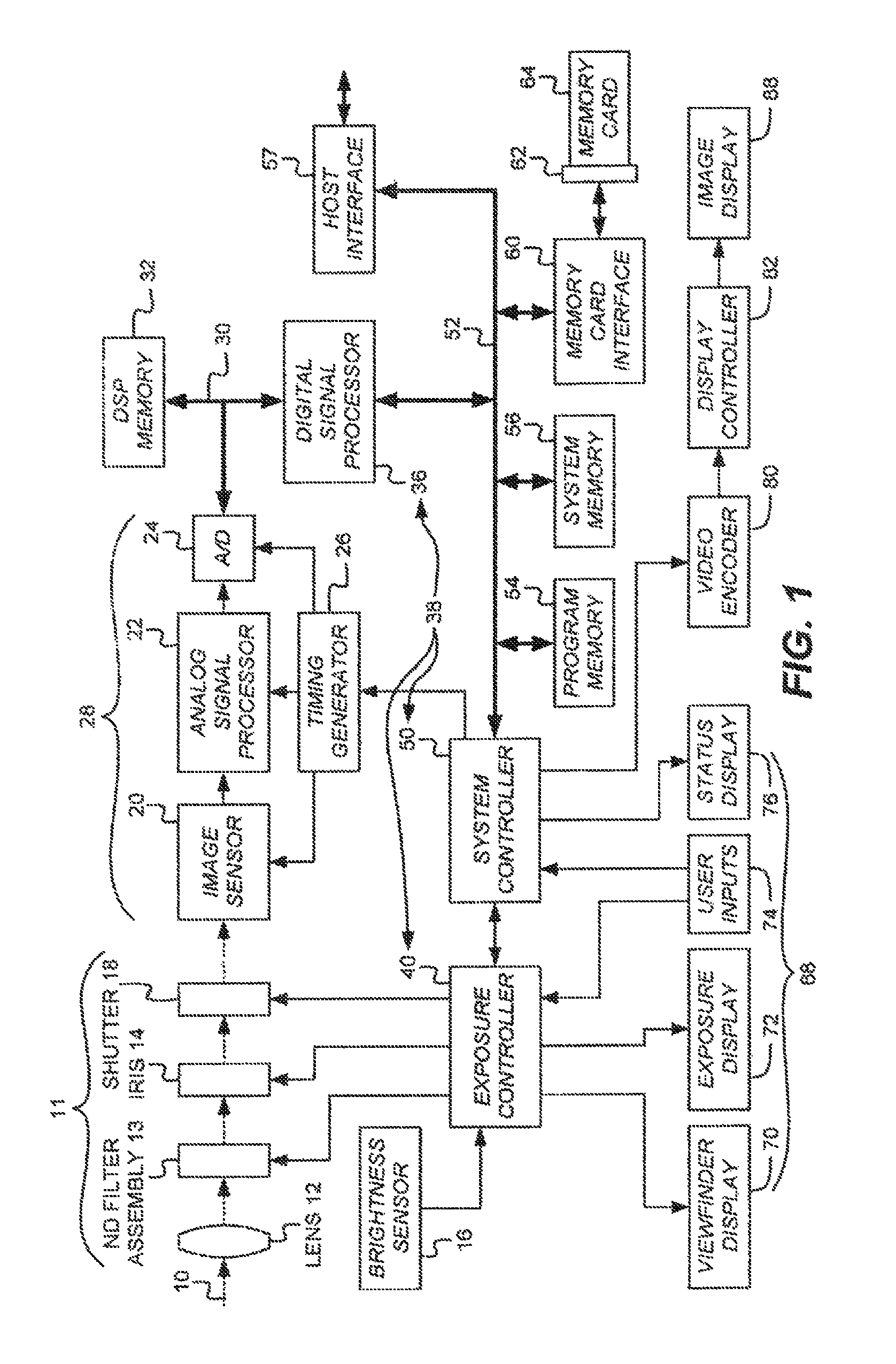
[0049]Because digital cameras employing imaging devices and related circuitry for signal capture and correction and for exposure control are well known, the present description will be directed in particular to elements forming part of, or cooperating more directly with, method and apparatus in accordance with the present invention. Elements not specifically shown or described herein are selected from those known in the art. Certain aspects of the embodiments to be described are provided in software. Given the system as shown and described according to the invention in the following materials, software not specifically shown, described or suggested herein that is useful for implementation of the invention is conventional and within the ordinary skill in such arts.

[0050]Turning now to FIG. 1, a block diagram of an image capture device shown as a digital camera embodying the present invention is shown. Although a digital camera will now be explained, the present invention is clearly a...


PUM


Abstract

A method for producing a digital image from pixel signals captured by an image sensor array is disclosed. The method includes: providing an image sensor array having at least two groups of pixels wherein the pixels of each group are uniformly distributed over the sensor; exposing the image sensor array to scene light and reading pixel charge from only the first group of pixels to produce a first set of pixel signals; after producing the first set of pixel signals, exposing the image sensor array, and then reading pixel charge from the second group of pixels and reading again pixels from the first group to produce a second set of pixel signals; and using the first and second sets of pixel signals to produce the digital image.

Description

CROSS-REFERENCE[0001]Reference is made to commonly-assigned U.S. patent application Ser. No. 11 / 780,523 filed Jul. 20, 2007 entitled “MULTIPLE COMPONENT READ OUT OF IMAGE SENSOR” to Hamilton, et al., the disclosure of which is incorporated herein.FIELD OF THE INVENTION[0002]The present invention relates to an image capture device using a two-dimensional image sensor array with multiple exposures and readouts to produce a digital image.BACKGROUND OF THE INVENTION[0003]In digital imaging, it is desirable to capture an image sequence having high image quality, high spatial resolution and high temporal resolution, also referred to as frame rate. With many current image sequence capture devices, however, it is not possible to obtain such high quality image sequences. In many cases, one of the desired image sequence attributes is obtained at the expense of the others. For example, in a conventional image sequence capture device, the exposure duration for a given image is limited by the fr...

Claims


Application Information

Patent Timeline
Patent Type & Authority Patents(United States)
IPC IPC(8): G03B7/00H04N5/235
CPCH04N5/3456H04N5/35581H04N5/35572H04N25/445H04N25/583H04N25/587H04N25/589H04N25/133H04N25/135
Inventor DEEVER, AARON T.PILLMAN, BRUCE H.COMPTON, JOHN T.ENGE, AMY D.
Owner OMNIVISION TECH INC
Why Eureka
Try Eureka