
Method for adjusting image

a technology of image frame and adjustment method, which is applied in the field of adjustment image, can solve the problems of not always at the optimal values of brightness, contrast, color saturation of the screen, and the inability of certain correction methods achieving better image frame quality to apply to models with hardware resources, and achieve the effect of reducing hardware resources, consuming hardware resources, and reducing hardware resources

Active Publication Date: 2012-07-10
MSI COMP SHENZHEN
View PDF7 Cites 6 Cited by
  • Summary
  • Abstract
  • Description
  • Claims
  • Application Information

AI Technical Summary

Benefits of technology

This approach allows for improved image adjustment with hardware resource consumption similar to the single curve method, effectively addressing the limitations of existing methods by reducing resource usage while enhancing image quality.

Problems solved by technology

However, when multimedia devices play video media, the brightness, contrast, and color saturation of the screens are not always at optimum values.
The current image processing technology has many different image frame adjusting methods, but such image frame adjusting methods can not bring high image quality with the lower hardware resources.
Certain correction methods achieving better image frame quality cannot be applied to the models having hardware resources, especially portable electronic products.
However, by only using the single image signal value adjusting curve equation, the variations in response to properties of films and relations among the image frames cannot be realized, so that the reinforcement effect is not distinct.
However, before the adjustment, the image must be analyzed first, such that higher hardware resources are required.
The major disadvantage of the quasi-HDR lies in requiring great hardware resources, such that high-level processors must be used together.
Among method for adjusting image in the prior art, a single curve method, a dynamic curve method, and a quasi-HDR method respectively have problems so that a reinforcement effect is poor or hardware resources are over-consumed.

Method used


Image

  • Method for adjusting image
  • Method for adjusting image
  • Method for adjusting image

Examples


Embodiment Construction

[0023]Please refer to FIG. 1, in which a method for adjusting image according to an embodiment of the present invention is applied to an image output device. The image output device may be a multimedia playing device, or a data processing device (for example, a personal computer), executing a multimedia playing program.

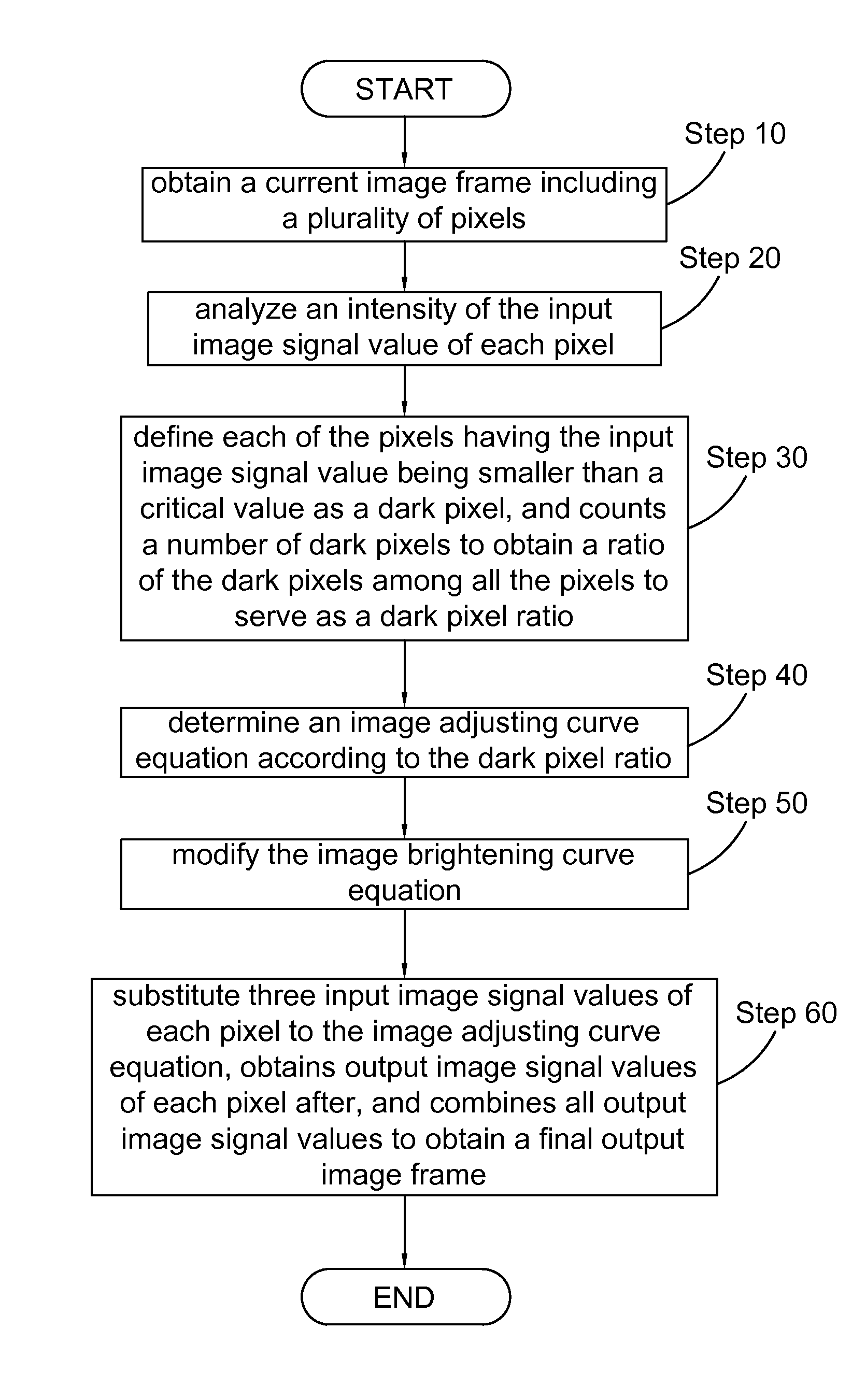
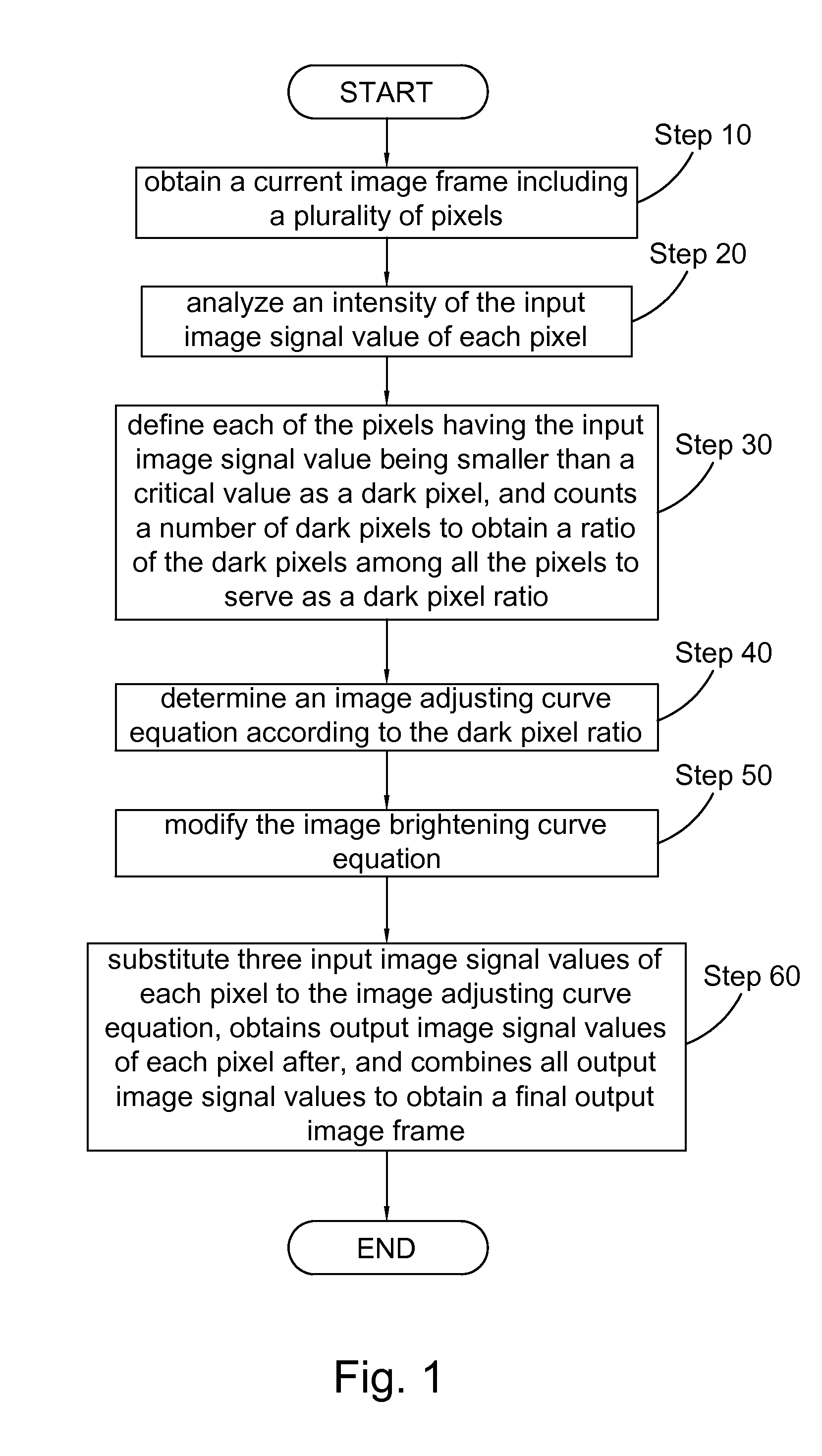
[0024]Please refer to FIG. 1, in which according to the method, the image output device firstly obtains a current image frame including a plurality of pixels (Step 10). Next, the image output device analyzes an intensity of the input image signal value of each pixel (Step 20).

[0025]Generally, a brightness of each pixel serves as the input image signal value, an intensity thereof is analyzed, and an obtained analysis result is used for performing image adjustment, so as to achieve a preferred image adjusting result. However, image signals output from a common electronic device are usually RGB color signals. If the brightness of each pixel is analyzed, the RGB color sig...


PUM


Abstract

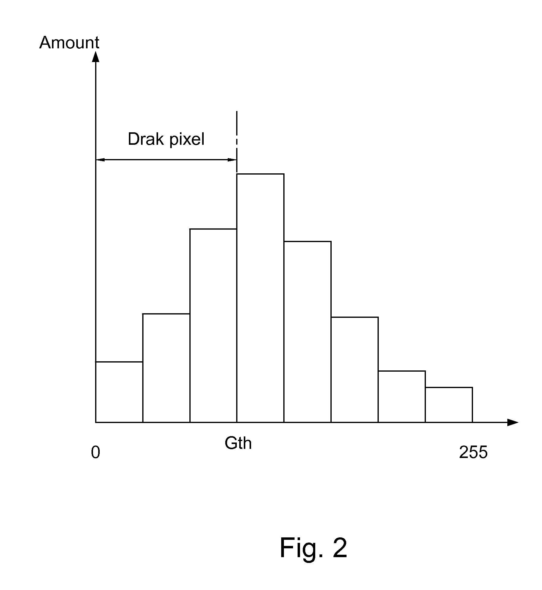
A method for adjusting image is applied to an image output device. According to the method, the image output device firstly obtains a current image frame including plural pixels, and analyzes an intensity of an input image signal value of each pixel. The image output device defines each pixel having the input image signal value being smaller than a critical value as a dark pixel, and counts a number of the dark pixels to obtain a ratio of the dark pixels among all the pixels to serve as a dark pixel ratio. The image output device determines an image adjusting curve equation according to the dark pixel ratio, substitutes the input image signal values to the image adjusting curve equation, and obtains output image signal values of the pixels. Finally, the image output device combines all the output image signal values to obtain a final output image frame.

Description

CROSS-REFERENCES TO RELATED APPLICATIONS[0001]This non-provisional application claims priority under 35 U.S.C. §119(a) on Patent Application No. 98143068 filed in Taiwan, R.O.C. on 2009 / 12 / 16, the entire contents of which are hereby incorporated by reference.BACKGROUND OF THE INVENTION[0002]1. Technical Field[0003]The present invention relates to a method for adjusting image, and more particularly to a method for adjusting image capable of improving an adjustment performance by using lower hardware resources.[0004]2. Related Art[0005]With the rapid progress of technology, liquid crystal displays or plasma display has replaced conventional cathode-ray tube (CRT) displays. Furthermore, the LCD displays has been widely applied to electronic products having different sizes. However, when multimedia devices play video media, the brightness, contrast, and color saturation of the screens are not always at optimum values. In addition, the video image frame is sometimes bright and sometimes ...

Claims


Application Information

Patent Timeline
Patent Type & Authority Patents(United States)
IPC IPC(8): H04N5/14
CPCH04N5/57H04N21/4318H04N21/44008
Inventor LO, KAI-WENYANG, REN-JIE
Owner MSI COMP SHENZHEN
Learn More