Servo-type vibration detector

a vibration detector and servo-type technology, applied in the direction of acceleration measurement using interia force, specific gravity measurement, instruments, etc., can solve the problems of difficult to detect whether or not a contact, difficult to recognize whether or not a detection limit of the vibration detector is exceeded, and cannot be easily removed for inspection and maintenance, etc., to achieve accurate determination of properties and statuses

Active Publication Date: 2012-07-17
MITUTOYO CORP
View PDF8 Cites 1 Cited by
  • Summary
  • Abstract
  • Description
  • Claims
  • Application Information

AI Technical Summary

Benefits of technology

[0010]In order to address the above-described conventional problems, the present invention provides a servo-type vibration detector capable of accurately determining properties and statuses of the vibration detector.
[0014]The present invention can provide the servo-type vibration detector capable of accurately determining properties and statuses of the vibration detector.

Problems solved by technology

Since the vibration detector is mostly mounted to a location difficult to directly access, such as in the earth or inside the apparatus, it can not be easily removed for inspection and maintenance.
It is thus not easy to detect whether or not a contact is made, particularly when the contact is momentary.
It is difficult to recognize whether or not a detection limit of the vibration detectors is exceeded.
In addition, even when a rate of acceleration within a detectable range of the vibration detectors is applied to the pendulum in the above-described test with test vibration, the electrodes may collide in a case in which a structure of the vibration detectors is deformed due to aging degradation of the vibration detectors or a significant impact thereto.
It is also difficult to easily determine a contact of the electrodes under the circumstance above, thus leading to an erroneous decision on whether the vibration detectors need to be replaced.

Method used


Image

  • Servo-type vibration detector
  • Servo-type vibration detector
  • Servo-type vibration detector

Examples


Embodiment Construction

[0019]The particulars shown herein are by way of example and for purposes of illustrative discussion of the embodiments of the present invention only and are presented in the cause of providing what is believed to be the most useful and readily understood description of the principles and conceptual aspects of the present invention. In this regard, no attempt is made to show structural details of the present invention in more detail than is necessary for the fundamental understanding of the present invention, the description is taken with the drawings making apparent to those skilled in the art how the forms of the present invention may be embodied in practice.

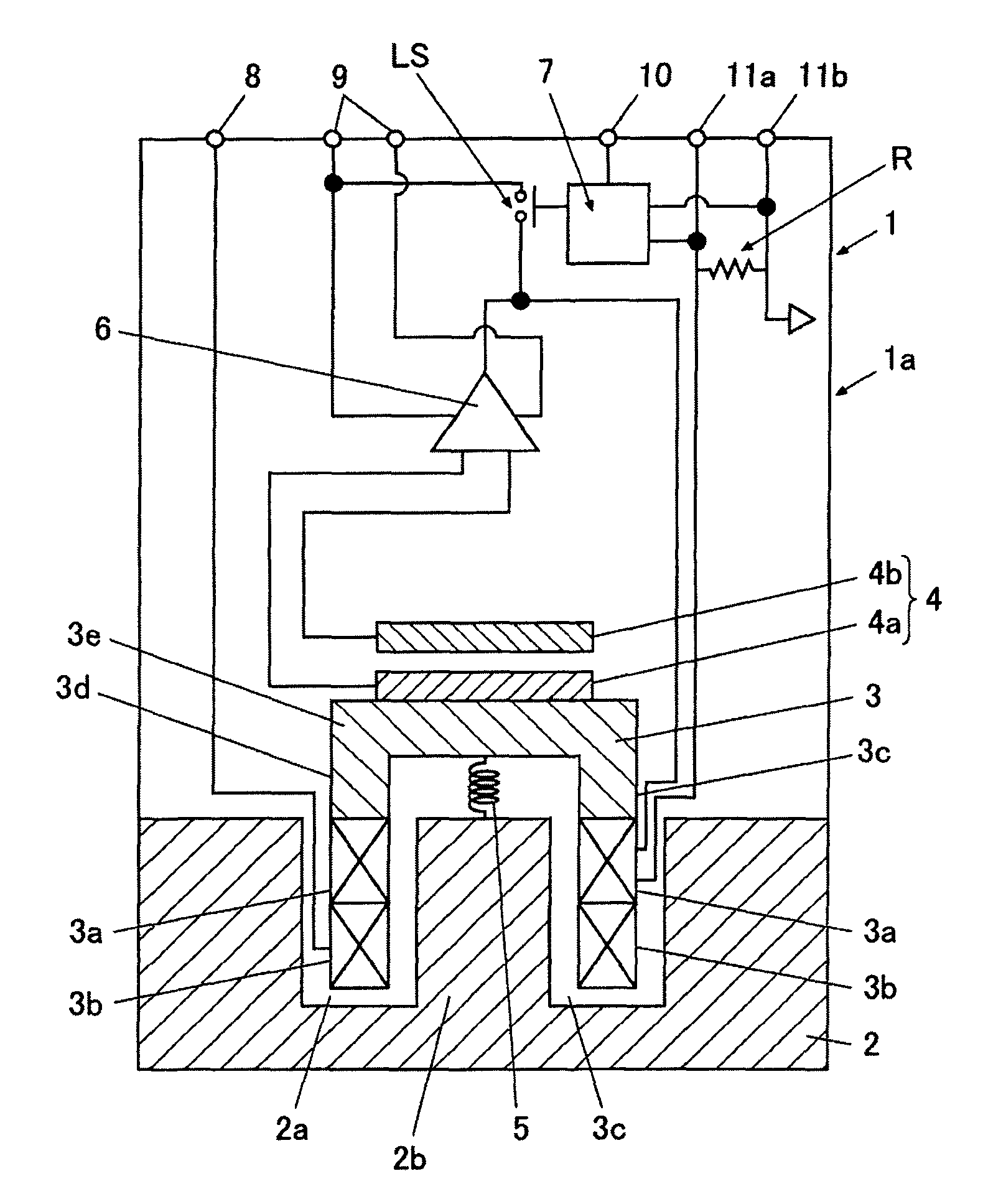
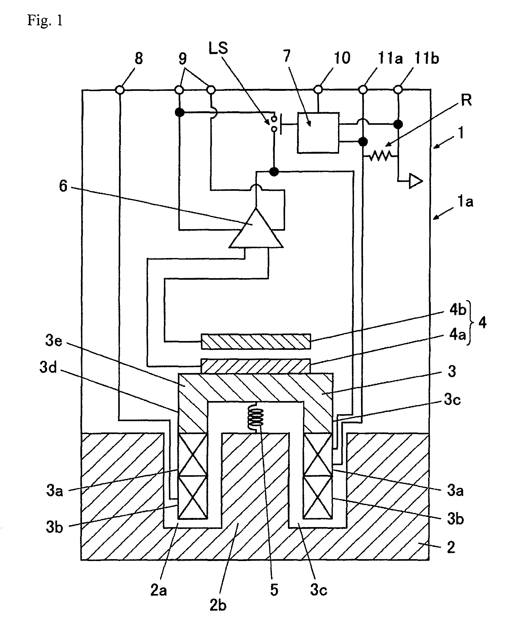
[0020]The embodiments of the present invention are explained below with reference to the drawings. FIG. 1 is a pattern diagram illustrating a schematic view of a vibration detector 1.

[0021]As shown in FIG. 1, the vibration detector 1 has a main body case 1a; a magnet 2 fixedly attached to the main body case 1a; a pendulum 3 di...


PUM


Abstract

A movable plate is provided to a pendulum displaceable by external vibration. A fixed plate is provided to a position opposite to the movable plate. A displacement detector detects an electrostatic capacitance between the plates. A servo amplifier supplies to a force coil, a current in an amount associated with the detection result. A current circuit and a load resistor of the force coil convert the current into a detection signal and output the signal. When the movable plate and the fixed plates, which are conducted to each other, are contacted, the electrostatic capacitance between the plates is removed. A processor detects a change in the detection signal due to the removal of the electrostatic capacitance, and then determines that the plates are contacted.

Description

CROSS-REFERENCE TO RELATED APPLICATIONS[0001]The present application claims priority under 35 U.S.C. §119 of Japanese Application No. 2009-155174 filed on Jun. 30, 2009, the disclosure of which is expressly incorporated by reference herein in its entirety.BACKGROUND OF THE INVENTION[0002]1. Field of the Invention[0003]The present invention relates to a servo-type vibration detector.[0004]2. Description of Related Art[0005]A conventional servo-type vibration detector is an apparatus that detects vibration using a servo mechanism, in which a position of a pendulum is controlled. When the pendulum is displaced because of external vibration, a current is supplied to a coil wound around the pendulum, and thereby the pendulum is held at a predetermined position. The current supplied to the coil at the time detects vibration amounts, such as a speed, a rate of acceleration, and the like.[0006]The servo-type vibration detector of this type is provided with a movable plate and a fixed plate,...

Claims


Application Information

Patent Timeline
Patent Type & Authority Patents(United States)
IPC IPC(8): G01H11/06
CPCG01H11/06
Inventor YAMADA, TOMOHARUNEMOTO, KIICHIRO
Owner MITUTOYO CORP
Why Eureka
Try Eureka