
Static electricity distribution measuring apparatus and static electricity distribution measuring method

a measuring apparatus and static electricity technology, applied in the direction of instruments, using reradiation, 2d-image generation, etc., can solve the problems of product manufacturing yield decline, product yield decline, manufacturing speed (manufacturing efficiency) decline, etc., to achieve easy comprehension, simple construction, and constant surface area

Active Publication Date: 2017-12-12
NAT INST OF ADVANCED IND SCI & TECH
View PDF14 Cites 0 Cited by
  • Summary
  • Abstract
  • Description
  • Claims
  • Application Information

AI Technical Summary

Benefits of technology

The static electricity distribution measuring apparatus has the ability to measure the static electricity on products with a constant surface area. It is simple in construction and easy to comprehend the results. It can make measurements quickly, which allows for accurate results. Additionally, it can measure static electricity on parts and products in real-time on a manufacturing line, for example. Overall, the apparatus provides a simple and efficient solution for measuring static electricity distribution.

Problems solved by technology

When there are flaws or defects in parts used in manufacturing products, or when there are flaws or defects in manufacturing procedures, the products that are manufactured naturally have flaws or defects, and the problem arises that manufacturing yields decline.
As problems relating to both the former and the latter, when operational flaws in various processes arise in automated manufacturing processes, the problems arise that manufacturing speed (manufacturing efficiency) declines and product manufacturing yields decline.
In contrast, in recent years companies have been spinning off manufacturing divisions (that is to say, manufacturing plants) due to problems with manufacturing costs, and manufacturing companies that undertake only subcontracted manufacturing have appeared.
When such separations exist, feedback and feedforward between the manufacturing site and the development site for quality deficiencies and declining yields at the manufacturing site are difficult.
As a result of this difficulty, there are concerns that manufacturing capabilities are declining in Japan's manufacturing industry (including fabless companies, manufacturing subsidiaries, contract manufacturing companies that handle only manufacturing, and / or the like).
There are a variety of causes of deterioration in product quality and yields at manufacturing sites.
There are inevitable causes such as simplicity in design and manufacturing, skill levels at the manufacturing site, the flow of manufacturing processes, manufacturing facilities, personal skills and / or the like, but one cause that tends to be overlooked is static electricity.
That is to say, there are various causes of defects or flaws in parts, products or manufacturing processes, and one cause is thought to be static electricity.
Despite such measures, the problem that parts and products used in manufacturing procedures carry static electricity has not been completely resolved.
Consequently, parts used in manufacturing such electronic equipment and precision equipment often carry static electricity and are easily damaged.
These parts have a certain size, and carrying static electricity, there are times when unpredictable behavior occurs.
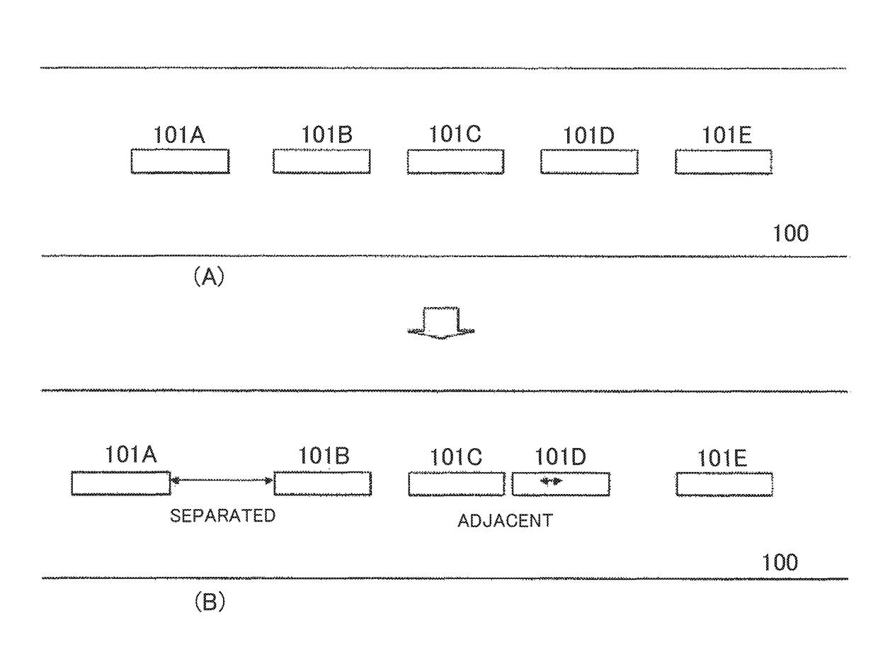
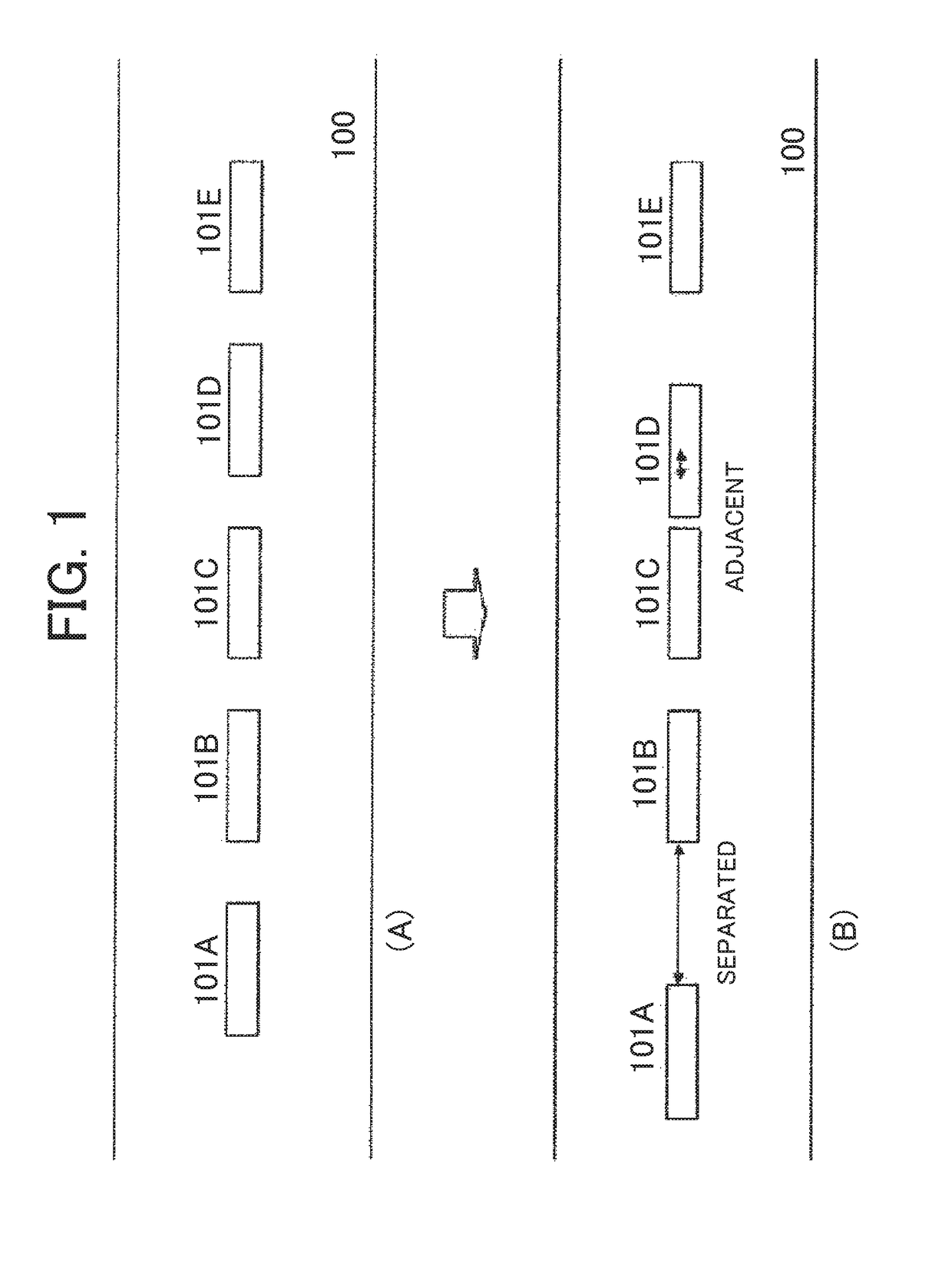
However, when such parts carry static electricity, movement is generated in the conveyor line as the parts draw closer to each other or are repelled from each other by static electricity.
When such behavior occurs, the appropriate processes cannot be done in the above-described arrangement procedure or external appearance inspection procedure.
When this kind of unpredictable behavior occurs in such parts in the arrangement procedure and the external appearance inspection procedure, it is necessary to temporarily halt the conveyor line.
When the conveyor line stops as a result of this charge-elimination work, a large loss is incurred in the manufacturing plant.
It is understood that static electricity is the cause of such parts giving rise to the above-described behavior, but the mechanism leading to the actual behavior is virtually unexplained.
Consequently, explaining the mechanism leading to the behavior is difficult when it is not known how the static electricity that is (thought to be) building up on parts is distributed in the parts.
If understanding the mechanism is difficult, it naturally follows that it is impossible to consider countermeasures to prevent the above-described behavior.
When such parts are used in assembly procedures for electronic equipment or precision equipment, when the parts inevitably carry static electricity, there are cases in which arrangement positions arbitrarily shift because of the static electricity.
When this occurs, the equipment being assembled naturally becomes flawed.
When this relationship is unknown, it is impossible to try resolving the problem.

Method used


Image

  • Static electricity distribution measuring apparatus and static electricity distribution measuring method
  • Static electricity distribution measuring apparatus and static electricity distribution measuring method
  • Static electricity distribution measuring apparatus and static electricity distribution measuring method

Examples


first exemplary embodiment

[0103]A first exemplary embodiment will be described.

[0104](Complete Overview)

[0105]FIG. 4 is a block diagram of a static electricity distribution measuring apparatus according to a first exemplary embodiment of the present disclosure. A static electricity distribution measuring apparatus 1 measures a static electricity distribution on the measurement target 200.

[0106]The measurement target 200 is various parts or products with the potential for building up static electricity as described above. For example, the measurement target 200 is any out of electronic parts, electronic elements, semiconductor integrated elements, electronic substrates, electronic equipment, machinery parts, transportation equipment, chemical products, foodstuffs, paper products, ceramic materials, plastic materials, polymer materials, film products, rubber products, resin products, metal products, pharmaceuticals and textile products, used at a manufacturing site. Naturally, these are examples, and other par...

second exemplary embodiment

[0177]Next, a second exemplary embodiment will be described.

[0178](Display)

[0179]FIG. 7 is a block diagram of a static electricity distribution measuring apparatus according to a second exemplary embodiment of the present disclosure. In addition to the same elements as FIG. 4, a display 7 is added. Description is omitted for elements having the same reference signs as in FIG. 4.

[0180]The display 7 displays a static electricity distribution diagram (for example, FIG. 6) drawn by the drawer 6. Through this display, the worker can easily understand visually the state of the static electricity distribution on the measurement target 200. For example, the display 7 may be a specialized monitor. Or, when the measurer 4 through drawer 6 are realized by a general-purpose personal computer, the monitor with which the personal computer is provided may fill the role of the display 7.

[0181]Because the display 7 is prepared, the worker can not only easily understand visually the static electricit...


PUM


Abstract

A static electricity distribution measuring apparatus (1) according to the present disclosure measures the static electricity distribution on a measurement surface of a measurement target (200), and is provided with: an array antenna (2) that receives electric fields generated from each of a plurality of areas (211) on the measurement surface through vibration; a vibrator (3) that vibrates the measurement target (200) or the array antenna (2); a measurer (4) that measures at least one from among intensity, frequency and phase of the electric fields in each of the plurality of areas (211) received by the array antenna (2); a calculator (5) that calculates an amount of static electricity for each of the plurality of areas (211) based on measurement results by the measurer (4); and a drawer (6) that draws the static electricity distribution on the measurement surface based on the amount of static electricity in each of the plurality of areas (211). The array antenna (2) has a plurality of antenna elements (21) respectively corresponding to the plurality of areas (211).

Description

TECHNICAL FIELD[0001]The present invention relates to a static electricity distribution measuring apparatus and a static electricity distribution measuring method for measuring and making visible a static electricity distribution in a part or product used during a manufacturing process, in a variety of manufacturing sites for manufacturing semiconductors, electronic equipment, precision machinery, transportation machinery, chemical products, foodstuffs and / or the like.BACKGROUND ART[0002]Japan has a variety of manufacturing industries that support the foundations of industry, such as manufacturing of semiconductors, electronic equipment, precision machinery, transportation machinery, chemical products, foodstuffs and / or the like. In factories that take charge of actual manufacturing in these kinds of manufacturing industries, products are assembled through automated procedures or manual procedures while numerous parts flow along production lines.[0003]When there are flaws or defects...

Claims


Application Information

Patent Timeline
Patent Type & Authority Patents(United States)
IPC IPC(8): G01R29/12G01R29/24G06T11/20G01R29/08G01V3/08G01R29/14H01L21/00G06F1/00G01H11/06
CPCG01R29/24G01H11/06G01R29/0878G01R29/14H01L2221/00G06F1/00G06T11/206H01L21/00G01V3/088
Inventor KIKUNAGA, KAZUYANONAKA, KAZUHIRO
Owner NAT INST OF ADVANCED IND SCI & TECH
Learn More