Beam mounted rear propulsion system for an aircraft and aircraft with such system

a rear propulsion system and beam technology, applied in the direction of aircraft power plants, aircraft power plants, aircraft power plant components, etc., can solve the problems of not necessarily presenting an optimum thrust balance, apu systems coming from the mass that they represent, and no solution has been implemented, so as to achieve optimal load transfer and significant rigidity of the carrying structure

Active Publication Date: 2012-07-17
AIRBUS OPERATIONS (SAS)
View PDF17 Cites 44 Cited by
  • Summary
  • Abstract
  • Description
  • Claims
  • Application Information

AI Technical Summary

Benefits of technology

[0017]More particularly, the disclosed embodiments relate to a structure for fixing a jet engine inside the rear part of an aircraft fuselage which is completely contained in the envelope of the fuselage tail cone and which allows to respect the constraints of safety as regards the fixing of the engine, particularly in the presence of the risk of engine bursting and allows an optimal operation of the concerned jet engine without aerodynamic penalty for the aircraft when the engine is not running.
[0025]In said propulsive system, the lateral beams are arranged along the walls within the fuselage tail cone in order to be used as a structure on which the secondary structure elements and boards of fuselage wall can take support and so that mechanical interferences with the external air supply device are avoided to allow the operation of air intake movable devices and not to generate internal aerodynamic disturbances in the air supply device.
[0027]In an example of arrangement of the beams, the half-beams of a same lateral beam are separated on at least a part of its length to form a fork ahead of attachments of the jet engine to the lateral beams to effectively meet the need to avoid mechanical interferences with the air supply device which is advantageously within the constituted fork.
[0028]To increase the resistance and the rigidity of the carrying structure and to fix secondary structures of the fuselage tail cone, the carrying structure also includes a higher beam substantially in a longitudinal, vertical symmetry plane of the fuselage, which higher beam, primarily for safety reasons, preferably includes at least two assembled half-beams.
[0032]A significant rigidity of the carrying structure and particularly an optimal transfer of loads due to the auxiliary jet engine are obtained by fixing the beams or half-beams on a front load carrying frame of the fuselage which corresponds to the sealed bottom of the pressurized cabin of the aircraft fuselage.
[0033]In order to optimize the installation of the aircraft empennages at the fuselage tail cone, the lateral beams, or their lower half-beams if necessary, are arranged so that the crossing structure of the horizontal empennage crosses the fuselage tail cone under the beams or lower half-beams of the carrying structure by providing the volumes needed for the displacements of the movable elements, and preferably vertical empennages are fixed at the ends of the horizontal empennage to avoid the deformation of the carrying structure of the auxiliary jet engine by the introduction of unsymmetrical efforts.

Problems solved by technology

While respecting the certification criteria and the operational constraints, the choice of the number and the characteristics of the engines is the result of compromises implying the desired, or required, performances of the aircraft in its various flying phases and in the various probable operating situations of the engines.
However, for industrial and operational reasons, the various engines of an aircraft in commercial exploitation are of the same model which has advantages in the field of the engines maintenance but does not present necessarily an optimum in term of thrust balance, carried mass for the propulsion and aerodynamic drag.
A drawback of the APU systems comes from the mass that they represent and which must be permanently transported mainly for a ground use.
However, this solution was never been implemented on an aircraft and, except using relatively small engines closer to a conventional APU than to an engine, many problems of mechanical installation and aerodynamic integration which are not solved today arise.

Method used


Image

  • Beam mounted rear propulsion system for an aircraft and aircraft with such system
  • Beam mounted rear propulsion system for an aircraft and aircraft with such system
  • Beam mounted rear propulsion system for an aircraft and aircraft with such system

Examples


Embodiment Construction

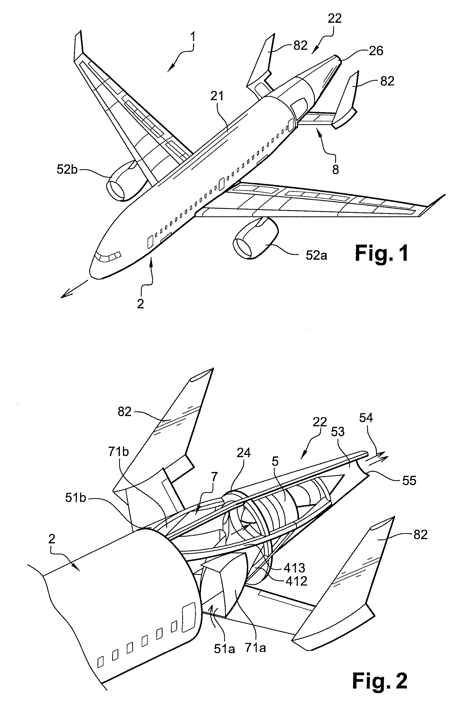
[0046]On an aircraft 1, shown in FIG. 1, according to the disclosed embodiments a fuselage 2, in a known way, comprises a substantially cylindrical central part 21 which is continued by a rear part 22 of the fuselage known as tail cone, rearwards along the displacement direction (materialized by an arrow directed forward on FIG. 1) of the aircraft during flight, whose sections decrease gradually from a section of the cylindrical part towards a final, relatively small, rear section.

[0047]In the following description of the aspects of the disclosed embodiments, it will be indicated by “front” and “rear” the aircraft forward direction along the flight displacement direction and respectively backward along the direction opposed to the flight displacement direction.

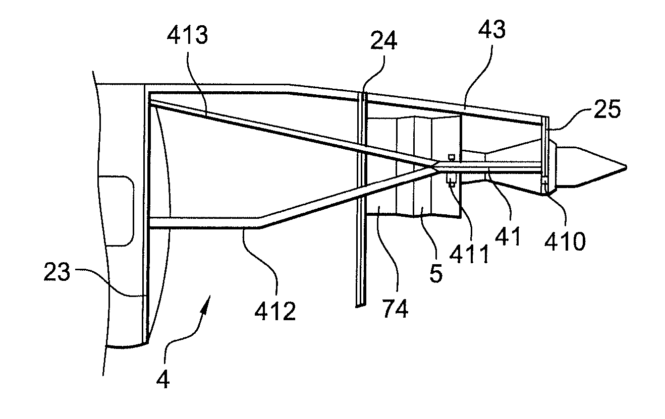
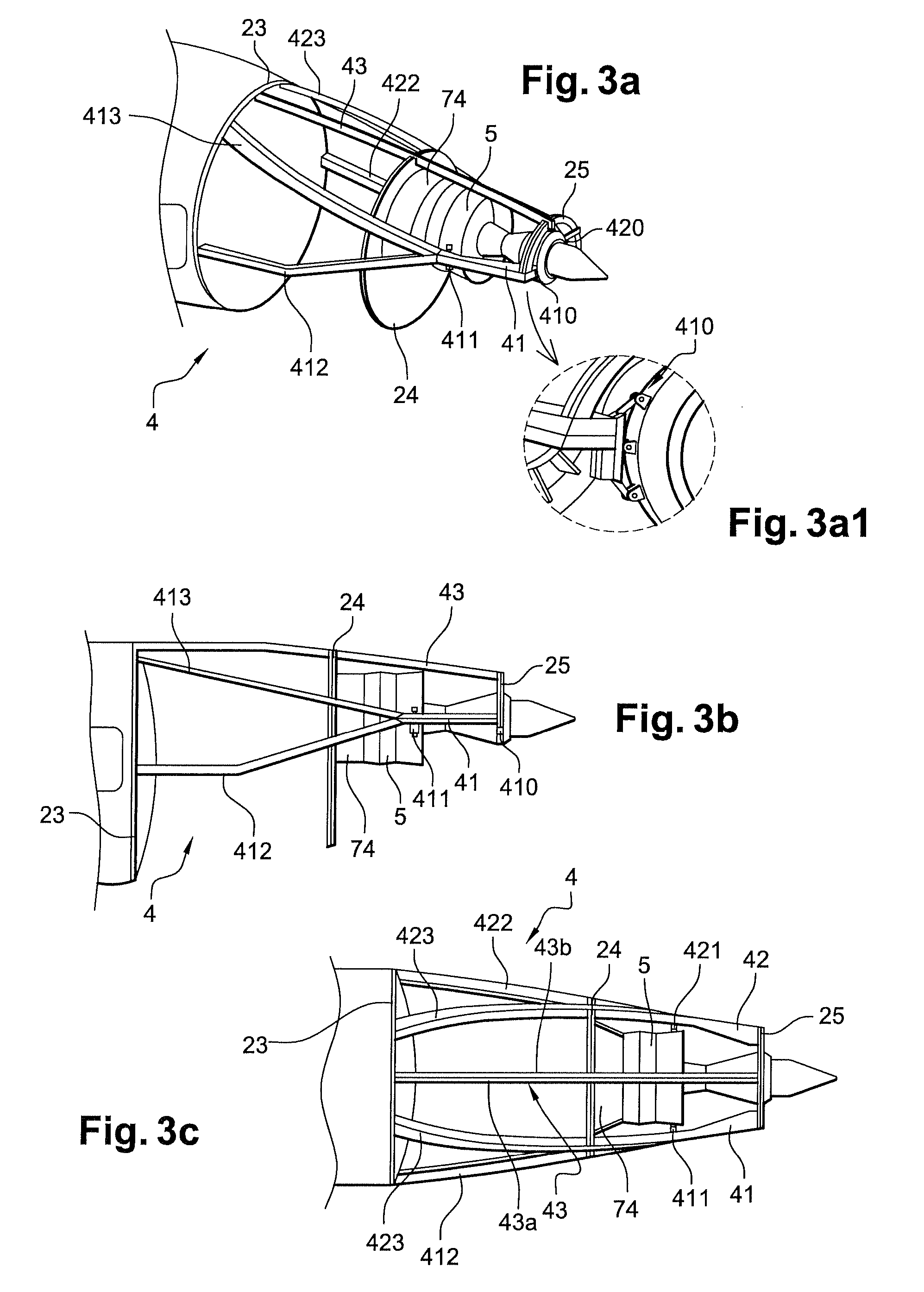
[0048]More particularly, in the auxiliary propulsive system according to the disclosed embodiments, the final section corresponds to an exit section of an auxiliary jet engine 5 fixed within the tail cone 22 as illustrated on ...


PUM


Abstract

A propulsive system for an aircraft including an auxiliary jet engine is integrated into a tail cone of a fuselage. A carrying structure of the jet engine is primarily formed with beams and frames or half-frames to which the auxiliary jet engine is fixed by lateral beams. The beams are interdependent of the frames and half-frames, and the beams are overhanging behind a frame behind which is fixed the engine. Each beam includes a lower half-beam and a higher half-beam, separated on at least a part of its length ahead from attachments of the jet engine to determine a space free of structure impediment for lateral air intakes.

Description

CROSS-REFERENCE TO RELATED APPLICATIONS[0001]This application claims priority to French application No. 08 51337 filed on 29 Feb. 2008, the disclosure of which is incorporated by reference herein in its entirety.BACKGROUND[0002]1. Field[0003]The disclosed embodiments belong to the field of aircraft powered by jet engines such as transport civil aircraft.[0004]More particularly the disclosed embodiments relate to an aircraft including at least an engine installed within the fuselage tail section in order to be used only in certain running phases of the aircraft on the ground or in flight.[0005]2. Brief Description of Related Developments[0006]For safety reasons and in order to fulfill the certification lawful requirements, the transport aircraft comprise two or several engines to survive to engine failure cases during the various flying, takeoff, cruising or approach and landing phases.[0007]While respecting the certification criteria and the operational constraints, the choice of th...

Claims


Application Information

Patent Timeline
Patent Type & Authority Patents(United States)
IPC IPC(8): B64D27/02B64D41/00B64D29/00
CPCB64D27/20B64D41/00B64D2033/0213B64D2041/002
Inventor CAZALS, OLIVIER
Owner AIRBUS OPERATIONS (SAS)
Why Eureka
Try Eureka