Eureka AIR delivers breakthrough ideas for toughest innovation challenges, trusted by R&D personnel around the world.

Image recording apparatus

a technology of image recording and recording tube, which is applied in the direction of electrographic process, instruments, transportation and packaging, etc., can solve the problems of increasing the size of the apparatus in the direction of the sheet conveyance, and achieve the effect of downsizing the apparatus

Active Publication Date: 2012-07-17
BROTHER KOGYO KK
View PDF19 Cites 25 Cited by
  • Summary
  • Abstract
  • Description
  • Claims
  • Application Information

AI Technical Summary

Benefits of technology

The present invention provides an image recording apparatus with a reduced size in the sheet conveyance direction. The apparatus includes a recording head, a conveying mechanism, a retaining portion, and a medium receiving portion. The recording head, retaining portion, and medium receiving portion are arranged in a vertical direction, which allows for a smaller size of the apparatus.

Problems solved by technology

In the image recording apparatus disclosed in the above Patent Document 1, the sheet retaining portion and the recording head are disposed side by side in the sheet conveyance direction, inevitably resulting in an increase in the size of the apparatus in the sheet conveyance direction.

Method used


Image

  • Image recording apparatus
  • Image recording apparatus
  • Image recording apparatus

Examples


Embodiment Construction

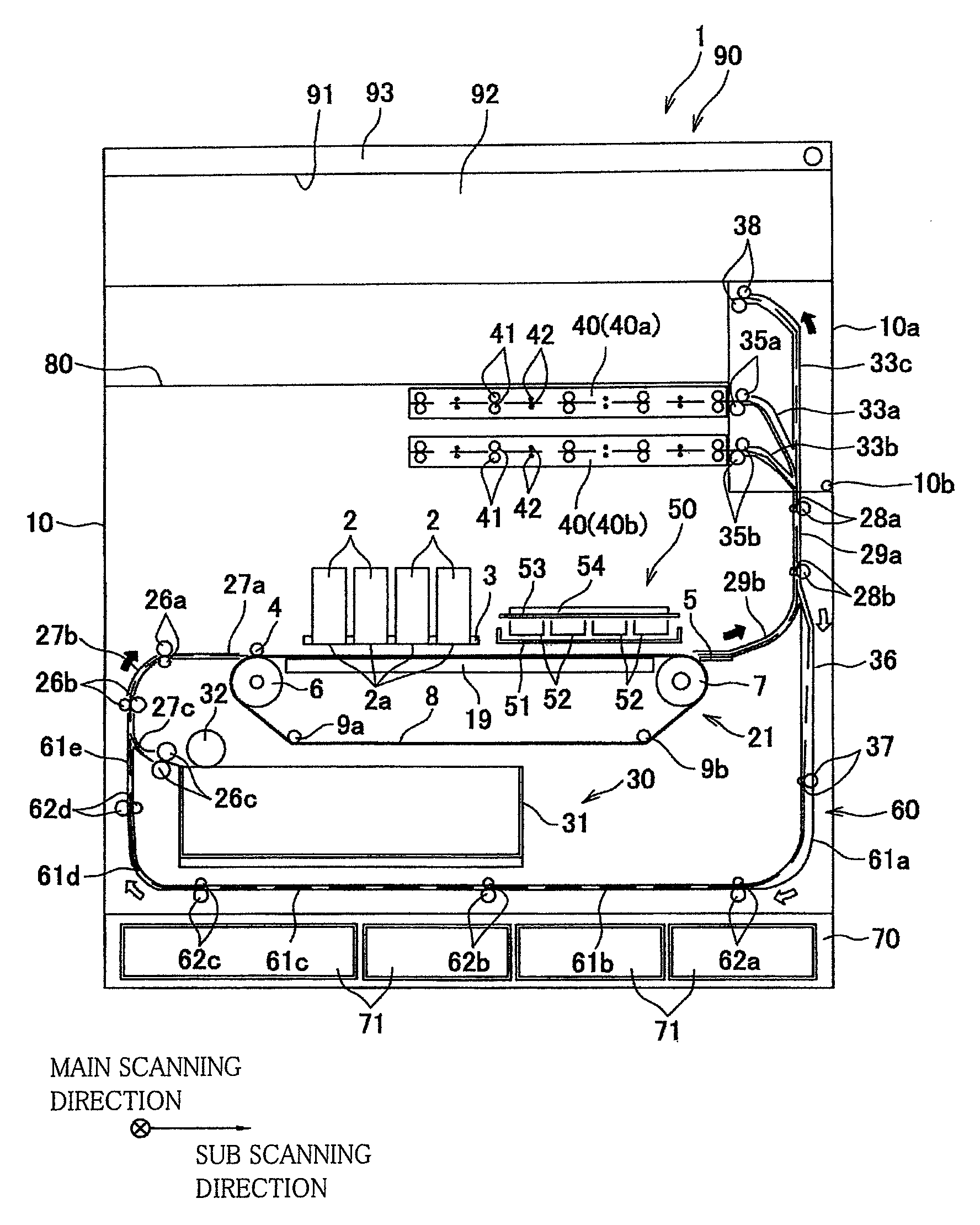
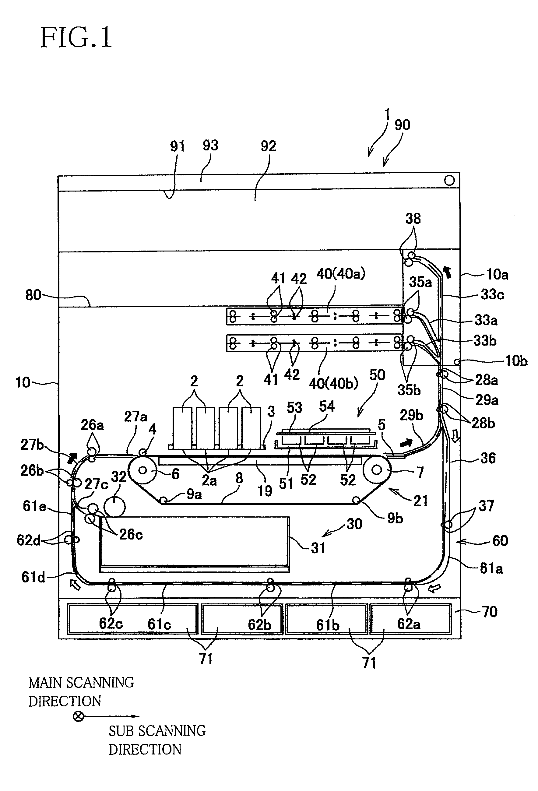
[0015]There will be hereinafter described a preferred embodiment of the invention with reference to the drawings. Referring to the schematic cross sectional view of FIG. 1, there will be explained an ink-jet printer according to the embodiment of the invention, to which the principle of the invention is applied. The ink-jet printer is configured to record characters and images on a recording sheet as a recording medium by ejecting ink thereon.

[0016]The ink-jet printer as an image recording apparatus generally indicated at 10 in FIG. 1 includes a casing 10 having an internal space. In the internal space of the casing 10, there are disposed, in order in a direction directing from the upper portion toward the lower portion of the internal space of the casing 10, two sheet retaining units 40 (each as a retaining portion) aligned with each other in the vertical direction, four ink jet heads 2 and a maintenance unit 50 which are disposed side by side in a sub scanning direction (i.e., in ...


PUM

PropertyMeasurementUnit
lengthaaaaaaaaaa
widthaaaaaaaaaa
sizeaaaaaaaaaa

Abstract

An image recording apparatus, including: a recording head configured to record an image on a recording medium; a conveying mechanism disposed so as to face the recording head and configured to convey the recording medium in a medium conveyance direction that is substantially horizontal; a retaining portion disposed configured to hold and retain the recording medium on which the image has been recorded by the recording head, such that the recording medium is held and retained in a substantially horizontal posture; and a medium receiving portion to which the recording medium on which the image has been recorded by the recording head is discharged,wherein the recording head, the retaining portion, and the medium receiving portion are arranged in a vertical direction.

Description

CROSS REFERENCE TO RELATED APPLICATION[0001]The present application claims priority from Japanese Patent Application No. 2008-247951, which was filed on Sep. 26, 2008, the disclosure of which is herein incorporated by reference in its entirety.BACKGROUND OF THE INVENTION[0002]1. Field of the Invention[0003]The present invention relates to an image recording apparatus configured to record an image on a recording medium.[0004]2. Discussion of Related Art[0005]There has been disclosed in the following Patent Document 1 an image recording apparatus having a recording head of a serial type configured to move, during a recording operation, in a direction perpendicular to a sheet conveyance direction, i.e., to move in a main scanning direction. In the disclosed image recording apparatus, a sheet retaining portion is disposed on a downstream side of the recording head, and a sheet on which recording has been performed is retained by the sheet retaining portion such that the sheet is held fr...

Claims


Application Information

Patent Timeline
Patent Type & Authority Patents(United States)
IPC IPC(8): B65H39/10
CPCB41J29/023B65H29/60B65H2301/132B65H2301/517B65H2601/11B65H2601/523B65H2801/12
Inventor YAMAMOTO, SHINYASUGIMOTO, KIYOSHI
Owner BROTHER KOGYO KK
Why Eureka
Eureka Blog
Learn More