Mehtod and apparatus for modifying object with electrons generated from cold cathode electron emitter

a technology of electron emitter and electron beam, which is applied in the direction of static indicating device, discharge tube main electrode, instruments, etc., can solve the problems of narrow application area of the apparatus, narrow device structure, and reduced treatment efficiency, and achieve the effect of reducing the modification cos

Inactive Publication Date: 2006-12-28
MATSUSHITA ELECTRIC WORKS LTD
View PDF8 Cites 23 Cited by
  • Summary
  • Abstract
  • Description
  • Claims
  • Application Information

AI Technical Summary

Benefits of technology

[0012] In the above apparatus, it is preferred that the first electrode is composed of an array of first electrode strips, which are arranged to be spaced from each other in a lateral direction, and the second electrode is composed of an array of second electrode strips, which are arranged to be spaced from each other in a direction intersecting with the lateral direction, wherein the electrons are selectively emitted from the planar electron emitting portion corresponding to an intersecting region(s) between at least one of the first electrode strips and at least one of the second electrode strips when the voltage is applied therebetween by the voltage applying unit. Furthermore, it is preferred that the apparatus has an first selector for selecting at least one of the first electrode strips, and a second selector for selecting at least one of the second electrode strips, wherein the voltage applying unit applies the voltage between at least one of the first electrode strips selected by the first selector and at least one of the second electrode strips selected by the second selector to selectively emit the electrons from the planar electron emitting portion corresponding to the intersecting region(s) therebetween. In this case, it is possible to change a modification area depending on the size of the object, thereby achieving energy saving and reducing the modification cost.

Problems solved by technology

This leads to a reduction in treatment efficiency, and a complication in device structure.
As a result, there is a problem that the application area of the apparatus is narrow despite an increase in cost of the apparatus.
In these methods, since an expensive electron accelerator is needed to obtain the high energy electron beam, a considerable increase in cost of the apparatus becomes a problem.
In addition, it has been difficult to irradiate such a high electron beam to a wide surface area of the object at a time.

Method used


Image

  • Mehtod and apparatus for modifying object with electrons generated from cold cathode electron emitter
  • Mehtod and apparatus for modifying object with electrons generated from cold cathode electron emitter
  • Mehtod and apparatus for modifying object with electrons generated from cold cathode electron emitter

Examples


first embodiment

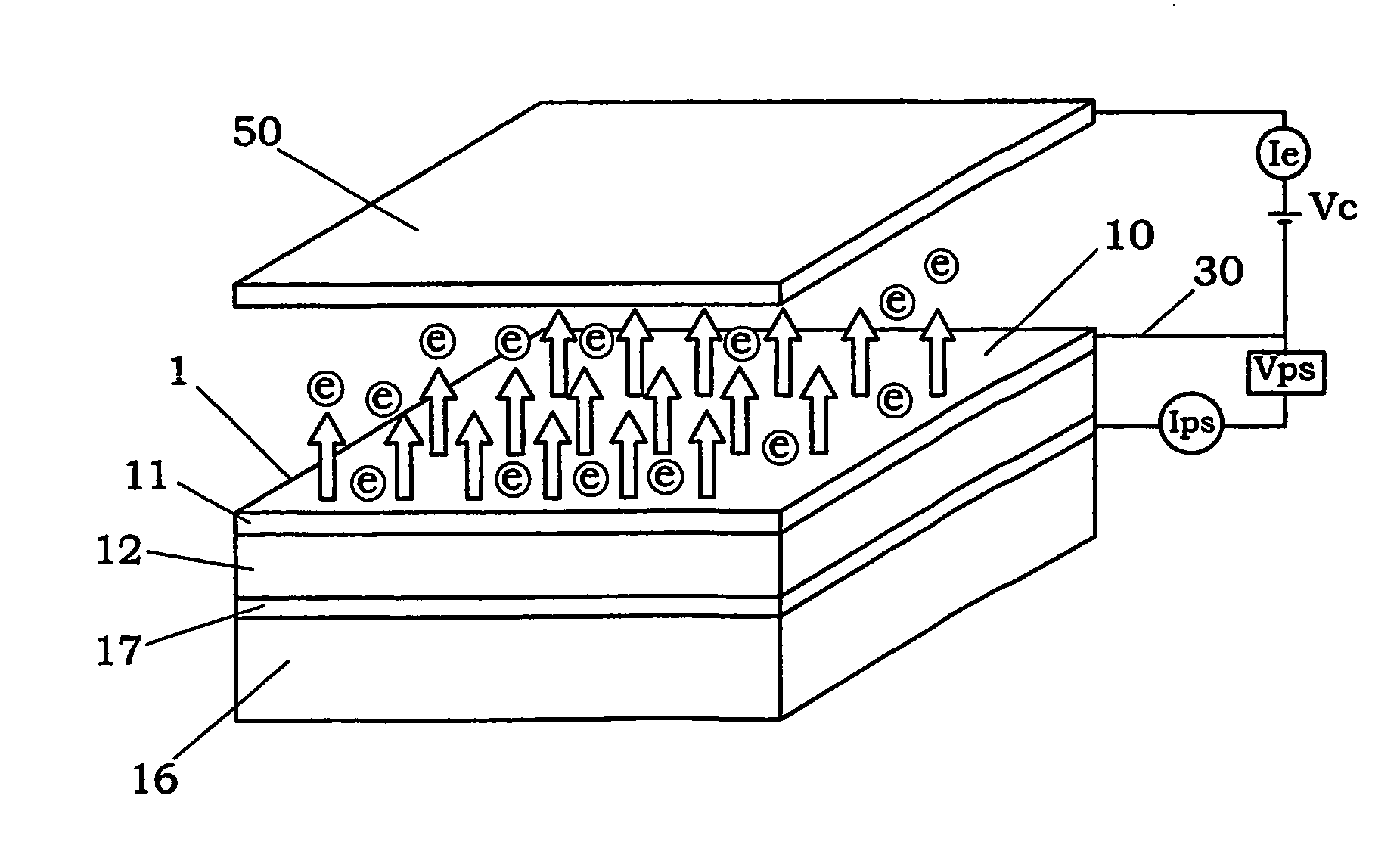
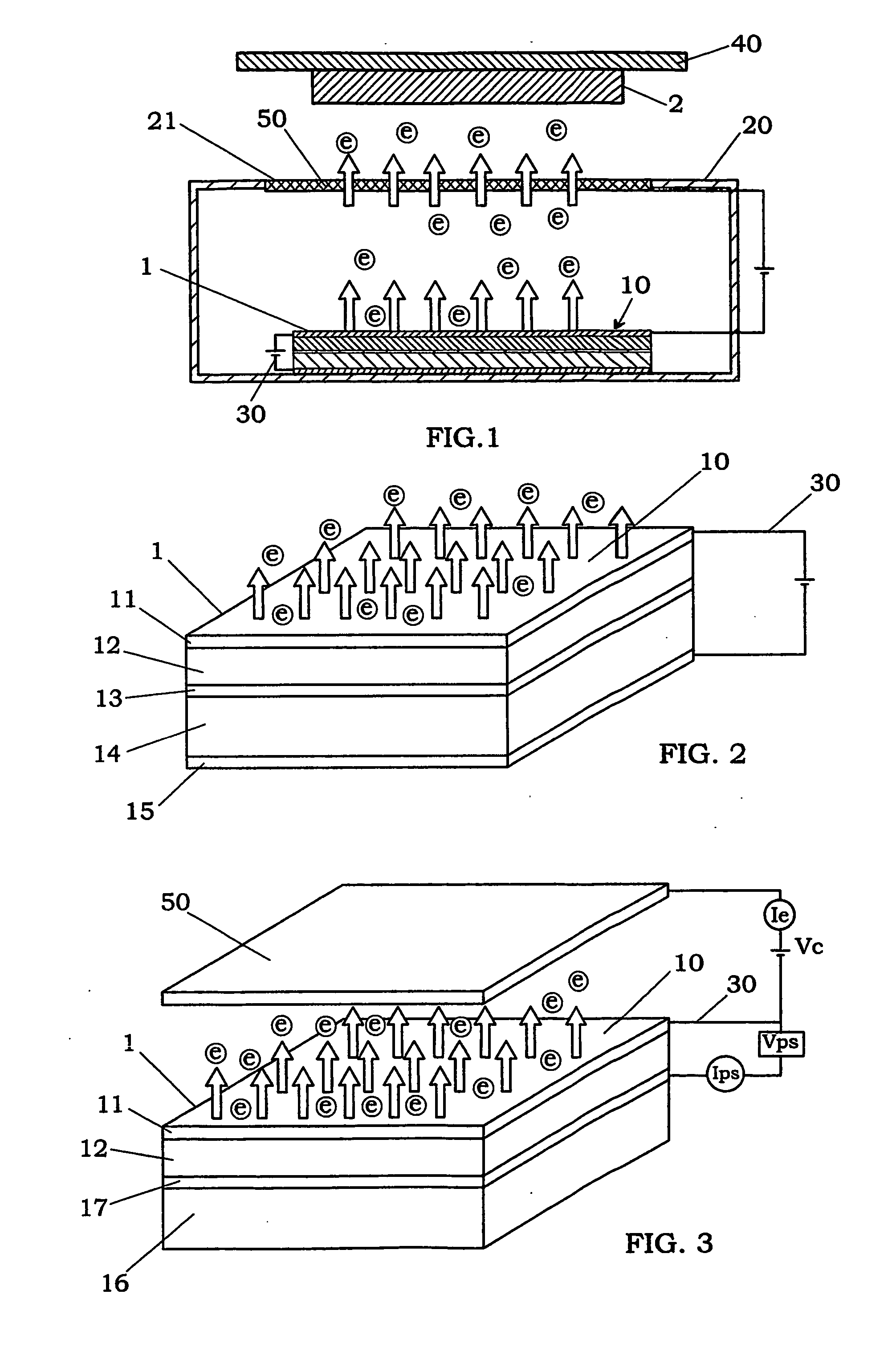
[0036] As shown in FIGS. 1 and 2, an apparatus for modifying an object 2 with electrons according to the present embodiment comprises a cold cathode electron emitter 1 having a planar electron emitting portion 10, a voltage applying unit 30 for applying a voltage to the emitter to emit electrons from the planar electron emitting portion, a case 20 for accommodating the emitter therein, which is made of an insulating material and has an opening 21 used to provide the emitted electrons to the outside of the case, and a holder 40 for supporting the object 2 such that the object is exposed to the electrons provided through the opening. In FIG. 1, the numeral 50 designates a mesh electrode attached to the opening 21 to accelerate the electrons generated from the emitter 1. Alternatively, a window member made of a material, through which the electrons can pass, may be attached to the opening in place of the accelerating electrode.

[0037] As shown in FIG. 2, the cold cathode electron emitt...

second embodiment

[0061] In this embodiment, apparatus and method for modifying a gas as the object by irradiation of electrons are explained.

[0062] As shown in FIG. 10, the modifying apparatus of this embodiment is characterized by comprising a case 20 having a gas inlet 22 for supplying the object gas into the case, and an opening 21 for providing a modified gas to the outside, and an acceleration electrode (anode electrode) 50 disposed in a face-to-face manner with an electron emitting portion 10 of a cold cathode electron emitter 1 in the case. The cold cathode electron emitter is the same as the emitter used in the first embodiment. Therefore, duplicate explanation is omitted. To avoid the influence of humidity on electron emitting efficiency of the cold cathode electron emitter, it is preferred that the gas supplied in the case 20 through the gas inlet 22 is a dry gas having a low moisture content. For example, it is preferred that the relative humidity (RH %) is smaller than 30%, and more pre...

third embodiment

[0069] In this embodiment, modifying apparatus and method for irradiating electrons to a gas or a gas containing liquid particles such as steam or moisture are explained.

[0070] That is, as shown in FIG. 15, this modifying apparatus is characterized by using a case 20 comprising gas inlets 22 for supplying a gas into the case, which are formed in lower portions of side walls of the case, and an opening 21 for ejecting electrons emitted from the cold cathode electron emitter 1, which is formed in a top wall at a position facing the electron emitting portion 10 of the cold cathode electron emitter placed on a bottom wall of the case. In addition, this apparatus has an accelerating electrode SO disposed above the opening, and a gas flow channel 70 provided on the top wall of the case 20. In this case, the gas is supplied as the object to the gas flow channel 70 from a gas supply unit 72, as shown by the horizontal arrow in FIG. 15, and then modified by the electrons accelerated from th...


PUM


Abstract

Apparatus and method for modifying an object with electrons are provided, by which the object can be uniformly and efficiently modified with the electrons under a pressure substantially equal to atmospheric pressure even when having a relatively wide surface area to be treated. This method uses a cold-cathode electron emitter having the capability of emitting electrons from a planar electron emitting portion according to tunnel effect, and preferably comprising a pair of electrodes, and a strong field drift layer including nanocrystalline silicon disposed between the electrodes. The object is exposed to electrons emitted from the planar electron emitting portion by applying a voltage between the electrodes. It is preferred that an energy of the emitted electrons is selected from a range of 1 eV to 50 keV, and preferably 1 eV to 100 eV.

Description

TECHNICAL FIELD [0001] The present invention relates to method and apparatus for modifying an object with electrons. BACKGROUND ART [0002] In the past, electron irradiation has been utilized to surface modify, sterilize or clean an object. For example, Japanese Patent Early Publication [kokai] No. 2002-6094 discloses an electron irradiating apparatus that can be used to form a cross-bridge structure or purify exhaust gas. This apparatus is provided with an electron gun having a hot filament, high-voltage power source for supplying an electric current to the hot filament to generate electrons, accelerating electrode for accelerating the generated electrons to obtain an electron beam, and an electromagnet for deflecting the electron beam. [0003] However, since the hot filament is an electron source having a spot-like or linear electron emitting portion, it is needed to scan the electron beam to modify a relatively wide surface area of the object. This leads to a reduction in treatment...

Claims


Application Information

Patent Timeline
Patent Type & Authority Applications(United States)
IPC IPC(8): G09G3/10B01J19/08G21K5/04H01J1/308H01J1/312H01J37/073H01J37/30
CPCB82Y10/00G21K5/04H01J37/30H01J1/312H01J37/073H01J1/308
Inventor AIZAWA, KOICHI
Owner MATSUSHITA ELECTRIC WORKS LTD
Why Eureka
Try Eureka