Optical assembly and optical-information-reading device

a technology of optical information and assembly, applied in the field of optical assembly, can solve the problems of difficult to downsize a device therefor, difficult to equip a small sized device such as a portable phone with such a mechanism, and the device to be downsized, so as to avoid a large increase in the amount of load and the effect of downsizing the devi

Inactive Publication Date: 2012-02-16
OPTO ELECTONICS CO LTD
View PDF1 Cites 21 Cited by
  • Summary
  • Abstract
  • Description
  • Claims
  • Application Information

AI Technical Summary

Benefits of technology

[0016]In the liquid-lens-optical assembly and the optical-information-reading device according to an embodiment of the present invention, by fixing the liquid lens through the elastic locating member, the load applied onto the liquid lens is restrained so that even if there is a tolerance in the parts, a fluctuation of the load is absorbed, thereby allow...

Problems solved by technology

For the autofocus function, moving a location of a lens along an optical axis mechanically has been known, but it is difficult for a small sized device such as a portable phone to be equipped with such a mechanism.
Since the liquid lens is typically susceptible to any load, it is necessary to...

Method used


Image

  • Optical assembly and optical-information-reading device
  • Optical assembly and optical-information-reading device
  • Optical assembly and optical-information-reading device

Examples


Embodiment Construction

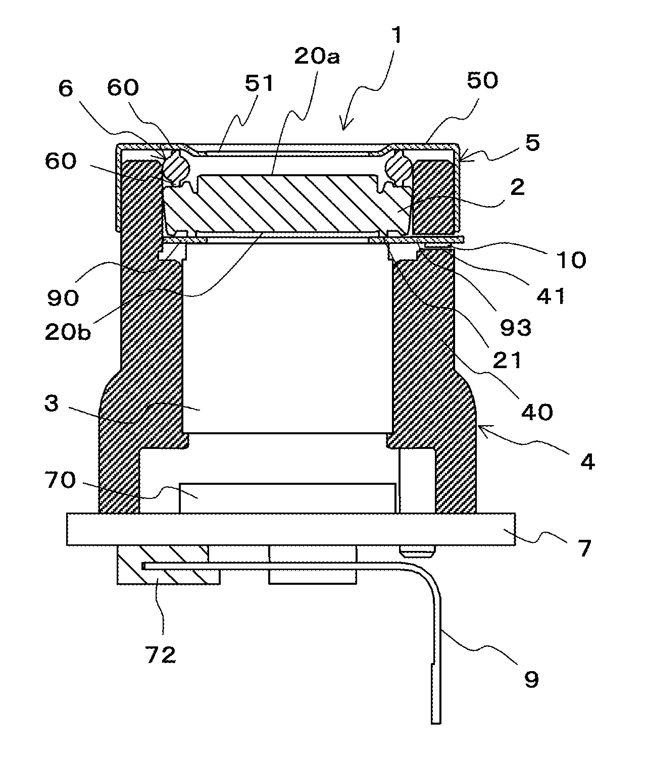
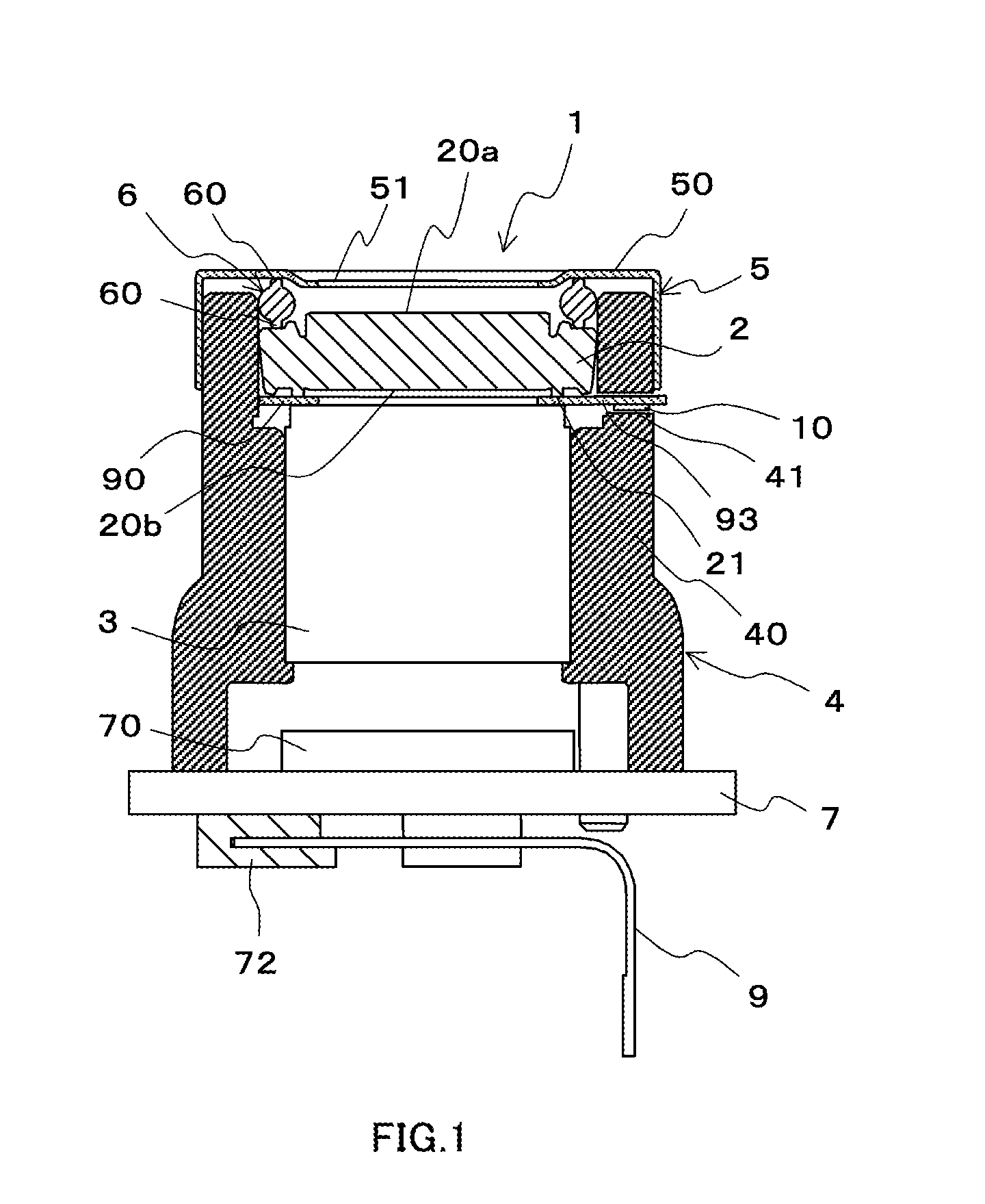
[0027]The following will describe embodiments of a camera module which is equipped with a liquid-lens-optical assembly according to the present invention and an optical-information-reading device which is provided with the camera module with reference to drawings.

(Configuration Example of Camera Module as Present Embodiment)

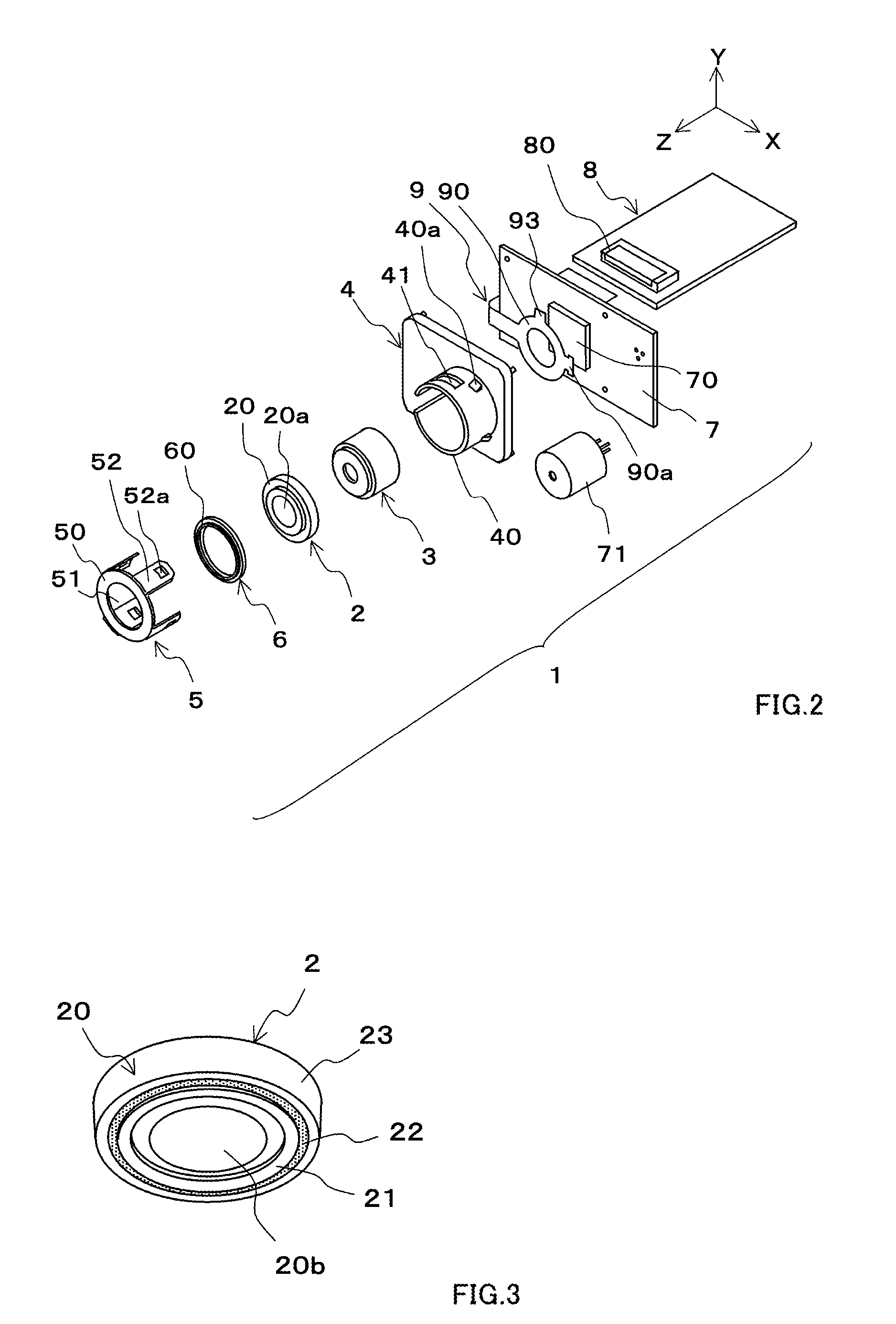
[0028]FIG. 1 is a sectional diagram showing an example of the camera module as the present embodiment; FIG. 2 is an exploded perspective diagram showing an example of the camera module as the present embodiment; FIG. 3 is an exterior and perspective diagram showing an example of a liquid lens constituting the camera module as the present embodiment; FIG. 4 is a perspective diagram showing an example of a flexible printed circuit substrate constituting the camera module as the present embodiment; FIGS. 5A and 5B are plan diagrams each showing an example of the flexible printed circuit substrate constituting the camera module as the present embodiment; and FIG. 6 i...


PUM


Abstract

To provide a camera module in which a liquid lens can be fixed with a simple configuration. The camera module 1 is provided with the liquid lens 2, a master lens 3 which is disposed at the same axle as that of the liquid lens 2. A camera body 4 has a lens-mounting portion 40 to which the liquid lens 2 and the master lens 3 are mounted with their optical axes aligned, and a lens cover 5 fixes the liquid lens 2 and the master lens 3 onto the lens-mounting portion 40. A ring-shaped packing 6 which is disposed between the lens cover 5 and the liquid lens 2 pushes the liquid lens 2.

Description

[0001]This patent application is a continuation of International Application No. PCT / JP2010 / 056259 filed Apr. 6, 2010 and designating the United States of America. This international application was published in Japanese on Oct. 14, 2010 under No. WO 2010 / 117003. This international application is hereby incorporated by reference in its entirety.BACKGROUND OF THE INVENTION[0002]The present invention relates to an optical assembly, preferably a liquid-lens-optical assembly, which is equipped with a liquid lens, and an optical-information-reading device which is provided with this liquid-lens-optical assembly.[0003]A bar code, which is one-dimensional code information for use in merchandise control, stock management or the like, has been well known. A two-dimensional code has also been known, as the code that has increased information density. Also known is a method of capturing the two-dimensional code with a solid-state image sensing device such as a CMOS image sensor or a CCD image ...

Claims


Application Information

Patent Timeline
IPC IPC(8): G06K7/14G02B3/12
CPCG02B3/14G02B26/005G03B13/36G03B17/02G03B17/14
Inventor KOMI, SATOSHI
Owner OPTO ELECTONICS CO LTD
Why Eureka
Try Eureka