Disk array apparatus

a technology of disk array and disk array, which is applied in the direction of electrical apparatus construction details, instruments, casings/cabinets/drawers, etc., can solve the problems of hardware performance degradation, hdd and others' lifetime, increase in power consumption, etc., to improve the cooling efficiency and the function of the entire apparatus, reduce noise and power consumption of the cooling fan, and reduce the effect of exhaust and cooling structur

Inactive Publication Date: 2007-07-10
HITACHI LTD
View PDF15 Cites 25 Cited by
  • Summary
  • Abstract
  • Description
  • Claims
  • Application Information

AI Technical Summary

Benefits of technology

[0008]The present invention is made in view of such problems described above, and an object of the present invention is to provide an efficient exhaust and cooling structure for solving the problems of lifetime of components (HDD and others) in a disk array apparatus. More specifically, the first object thereof is to provide a technology capable of improving the cooling efficiency and the function of the entire apparatus, and the second object thereof is to provide a technology capable of reducing the noise and power consumption of the cooling fan and the like.
[0016]The effects obtained by typical aspects of the present invention will be briefly described below. According to the present invention, an efficient exhaust and cooling structure capable of solving the problem of the lifetime of the components (HDD and others) in the disk array apparatus can be provided. In particular, first, it is possible to achieve the high cooling efficiency and cooling function in the entire apparatus. Second, it is possible to reduce the noise and the power consumption of the fan and others. Furthermore, it is possible to realize a simple and low-cost cooling system which can improve the degree of freedom of the design and mounting and can contribute to the downsizing of the apparatus.

Problems solved by technology

In the conventional technologies, the problems of the lifetime of the HDD and others and the performance degradation of hardware occur due to the increase in heat generation resulting from the density growth and the performance improvement.
Furthermore, there are also the problems of noise generated by the cooling system using the high-power exhaust fan and increase in power consumption due to the high power.

Method used


Image

  • Disk array apparatus
  • Disk array apparatus
  • Disk array apparatus

Examples


first embodiment

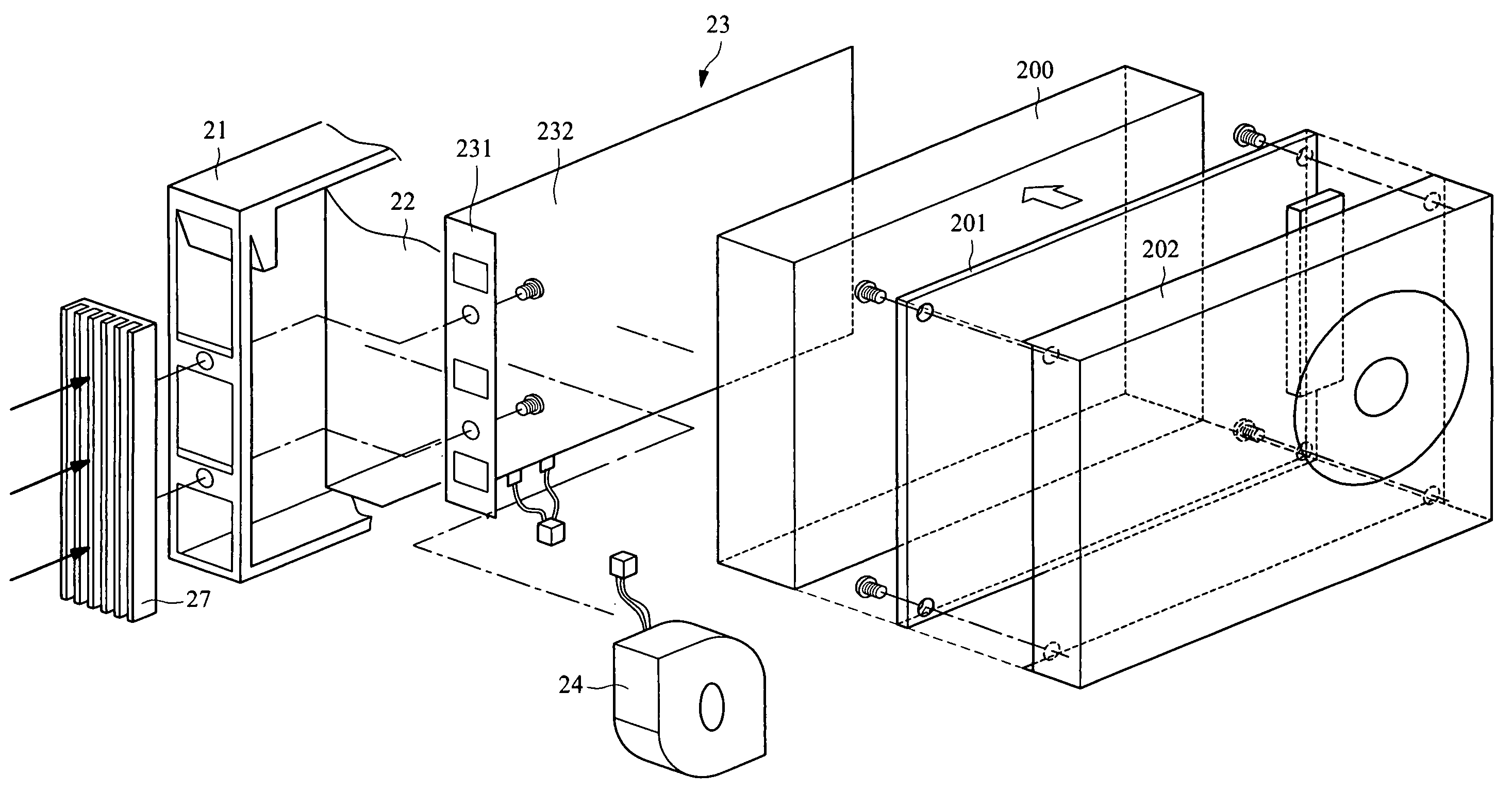
[0030]In the first embodiment, in brief, a structure in which a thermoelectric device 23, a cooling fan 24, an air duct 25 and others are attached to a HDD module 20 (see FIG. 3) will be described. The components including HDD 200 are cooled by the cooling fan 24 connected to the thermoelectric device 23 and an electrically-operated exhaust fan 35 (operated by main power supply of the apparatus) in an upper part of the chassis. The thermoelectric device 23 generates electric power by the thermoelectric conversion of the heat generated from the HDD 200. The cooling fan 24 is automatically operated by the power of the thermoelectric device 23. The air duct 25 supports the exhaust by the cooling fan 24 and the cooling of the predetermined parts (disk portion 202) of the HDD 200.

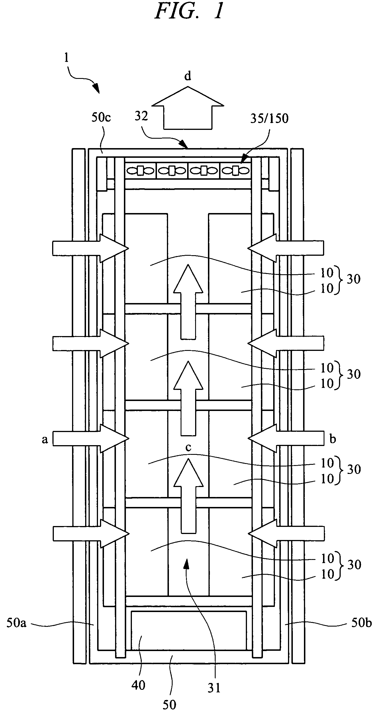
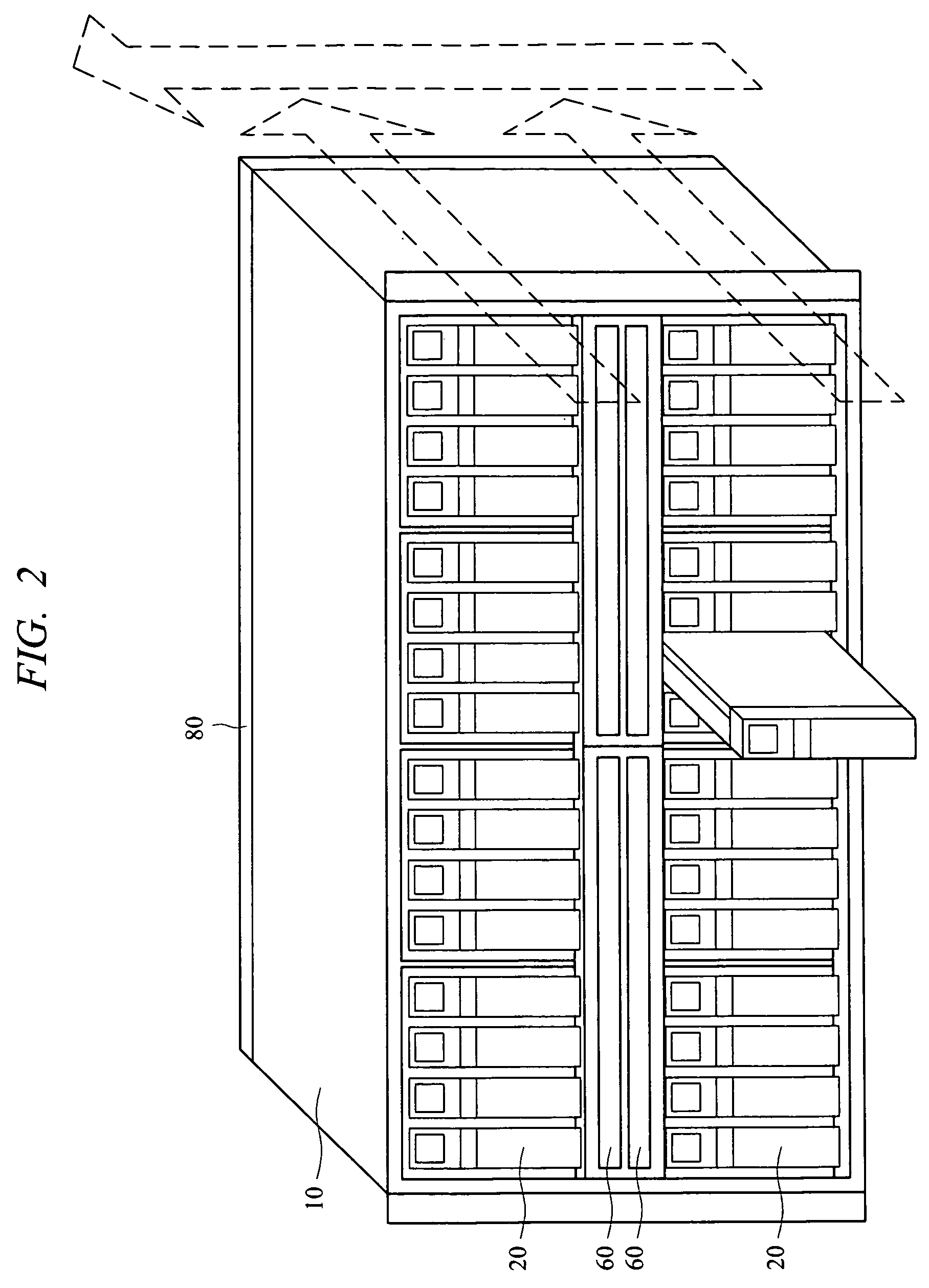
[0031]FIG. 1 is a diagram showing a disk array apparatus 1 and an entire structure of the ventilation path seen from side of the chassis in the first embodiment of the present invention. FIG. 2 is a diagram show...

second embodiment

[0075]Next, the second embodiment will be described. FIG. 8 shows the configuration of the disk array apparatus 1 according to the second embodiment, in which an exhaust fan control function is provided. FIG. 9 shows an example of the grouped structure in the HDD boxes 10 and others. In the first embodiment, the control system (DKC) of the disk array apparatus 1 does not have to perform the particular control (software process) for the above-described cooling structure, and the effects can be achieved automatically. The second embodiment has the basic structure similar to that of the first embodiment, and the control (software process) for the above-described cooling structure is performed. In particular, the function to control the exhaust fan section (150) in the upper part of the apparatus based on the temperature state of the HDD 200 (HDD module 20) is provided. Also, the control function corresponding to the grouped structure is provided.

[0076]In the second embodiment, the cont...

third embodiment

[0086]Next, the third embodiment will be described. The third embodiment basically has the structure similar to that shown in FIG. 8, and the control function for the upper exhaust fan 35 in consideration of the data access to the HDD 200 is provided. Furthermore, the control function corresponding to the grouped structure can be provided also in the third embodiment.

[0087]It is known that the temperature around the HDD 200 is increased by 0.5 to 1° C. by a unit data access such as the disk R / W access to the HDD 200 of the HDD module 20. In the third embodiment, the data access to the HDD 200 is monitored and detected by a predetermined control processor, and the rotation speed of the exhaust fan 35 corresponding to the location of the corresponding HDD module 20 is controlled to compensate the cooling by the cooling fan 24 built in the HDD module 20.

[0088]For example, as shown in FIG. 8, in the process by the program 61, the access to the HDD 200 is monitored and detected in the co...


PUM


Abstract

An efficient exhausting and cooling structure in a disk array apparatus is provided. A HDD module mounted in a HDD box of the disk array apparatus includes, around a HDD, a thermoelectric device which converts heat of HDD into electric power by using temperature difference, a cooling fan automatically operated by power supply of the thermoelectric device, and an air duct which directs air flowing and exhausted from the cooling fan to a rear face side of the HDD module. The entire apparatus is cooled and air therein is exhausted by the operation of exhaust fan operated by main power supply of the apparatus provided in an upper part of the chassis and the automatic operation of the cooling fan of each HDD module.

Description

CROSS-REFERENCE TO RELATED APPLICATION[0001]The present application claims priority from Japanese Patent Application No. JP 2005-377138 filed on Dec. 28, 2005, the content of which is hereby incorporated by reference into this application.TECHNICAL FIELD OF THE INVENTION[0002]The present invention relates to a technology for a disk array apparatus (also referred to as storage apparatus) having a function to control a storage device such as HDD (Hard Disk Drive). More particularly, it relates to an exhaust and cooling structure thereof.BACKGROUND OF THE INVENTION[0003]In a recent large-scale disk array apparatus, the density growth and the performance improvement associated with the space-saving have been developing. Accordingly, in order to solve the problem of the lifetime of a magnetic disk or the like due to the heat generated by the components themselves, the cooling system with a high-power exhaust fan mounted in an upper part of the disk array apparatus is employed.[0004]The c...

Claims


Application Information

Patent Timeline
Patent Type & Authority Patents(United States)
IPC IPC(8): H05K7/20H01L35/28H05K5/00
CPCG11B33/142H05K7/20736
Inventor TANAKA, SHIGEAKI
Owner HITACHI LTD
Why Eureka
Try Eureka