Fiber optic cable assemblies with mechanically interlocking crimp bands and methods of making the assemblies

a fiber optic cable and crimping technology, applied in the field of fiber optic cable assemblies, can solve the problems of optical fiber breakage, optical fiber attenuation, and signal strength degraded significantly

Active Publication Date: 2012-07-17
CORNING OPTICAL COMM LLC
View PDF43 Cites 9 Cited by
  • Summary
  • Abstract
  • Description
  • Claims
  • Application Information

AI Technical Summary

Problems solved by technology

Alignment issues can create optical attenuation and signal strength may be significantly degraded where misalignment exists.
If the cable is pulled off the connectors, the optical fibers will break and the cable assembly will be destroyed.
The alignment and cable attachment features of conventional cable assemblies sufficient protection against attenuation losses and do not provide sufficient resistance to cable pull off forces.

Method used


Image

  • Fiber optic cable assemblies with mechanically interlocking crimp bands and methods of making the assemblies
  • Fiber optic cable assemblies with mechanically interlocking crimp bands and methods of making the assemblies
  • Fiber optic cable assemblies with mechanically interlocking crimp bands and methods of making the assemblies

Examples


Embodiment Construction

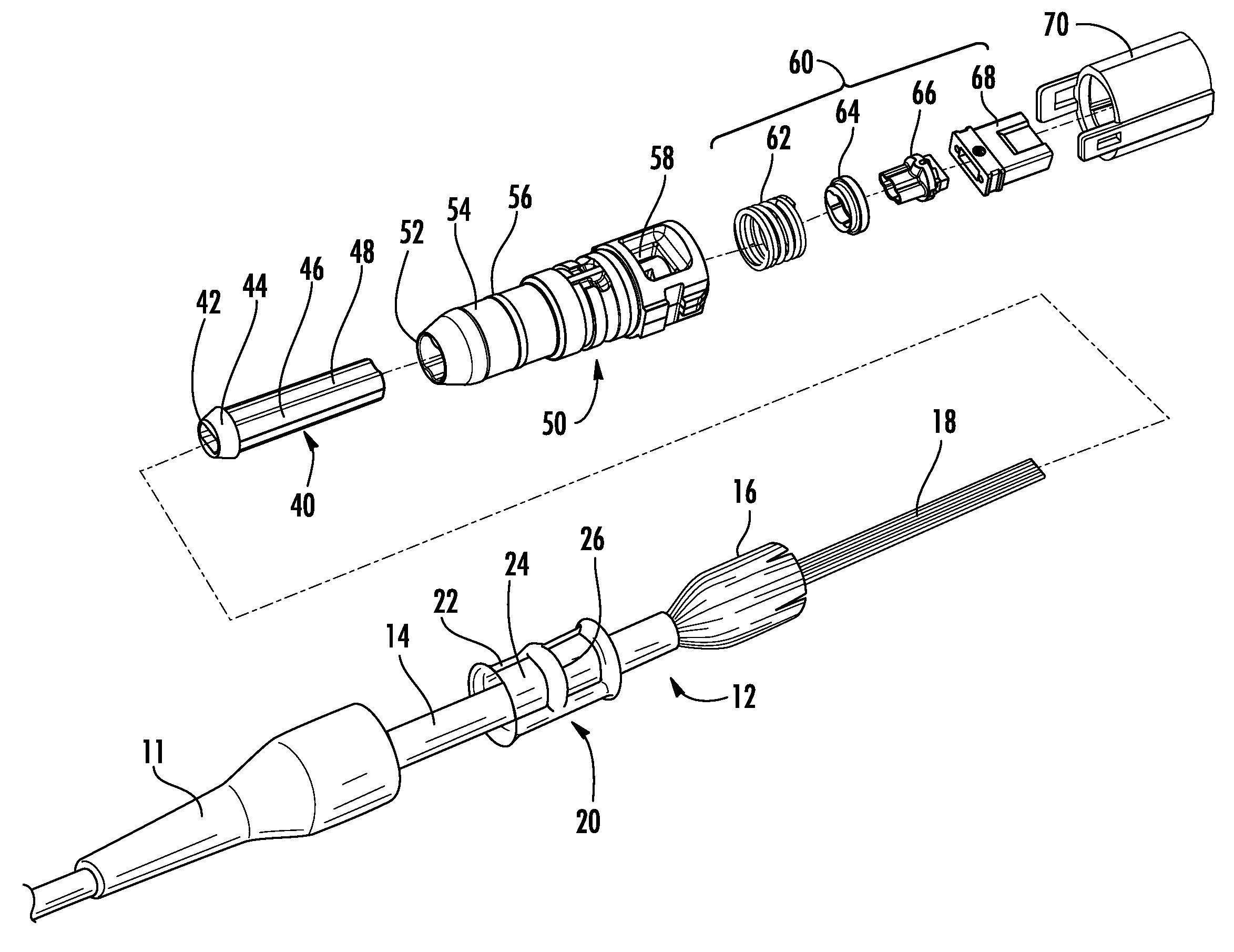
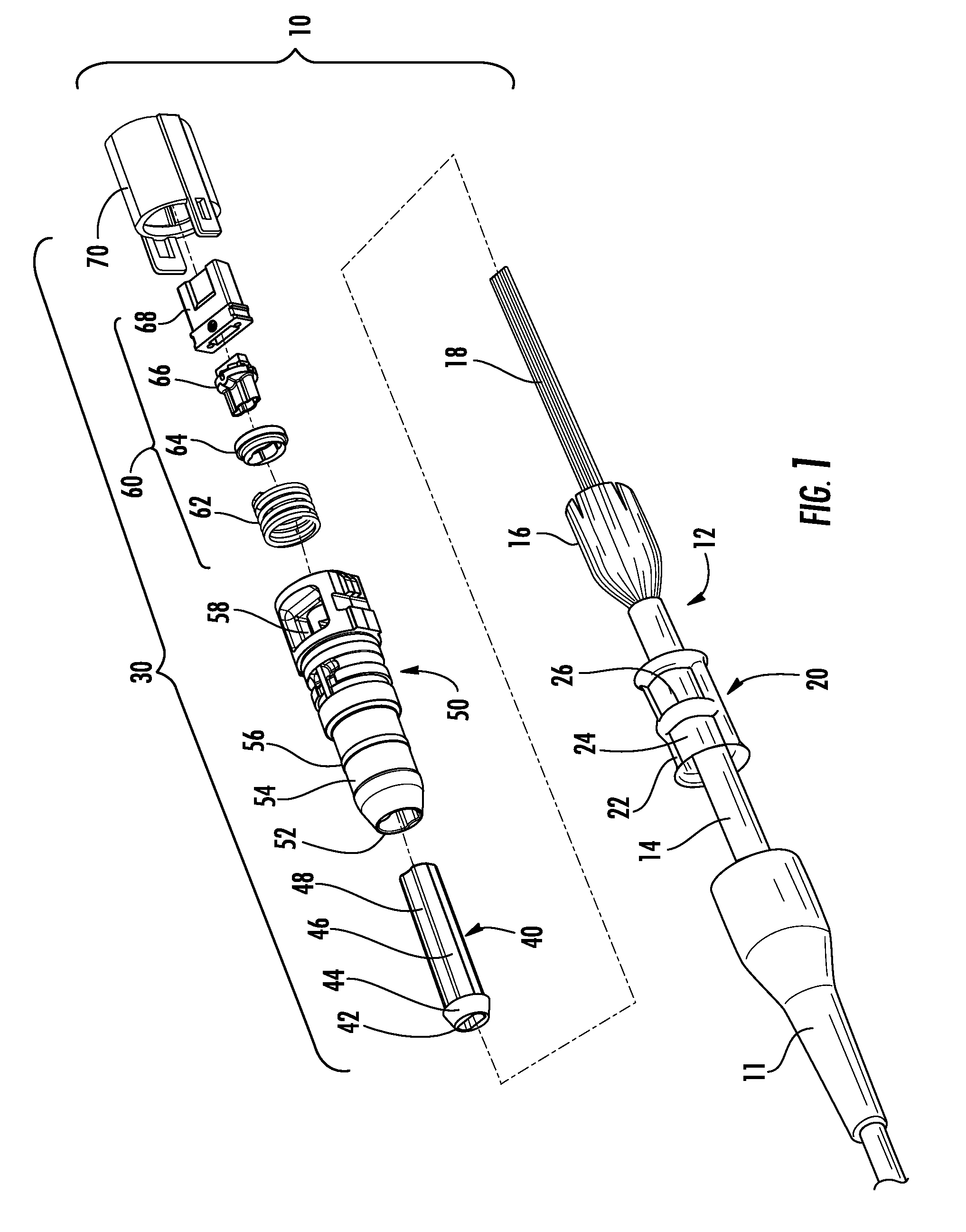
[0032]A crimp body is disclosed that cooperates with a crimp band for increased strength. The crimp body may be included in a fiber optic connector assembly, a fiber optic cable assembly, a splice assembly, or a furcation assembly. The crimp body has features that interlock with features on the crimp band to crimp a cable having fibrous strength elements to a suitable sub-assembly. The crimp body further may include an access aperture for optical fiber handling during assembly of the fiber optic cable assembly.

[0033]In an exemplary embodiment, a fiber optic cable sub-assembly 10 includes at least a boot 11, a fiber optic cable 12, a crimp band 20 and a connector sub-assembly 30 (FIG. 1). Connector sub-assembly 30 includes at least an optical fiber guide insert 40, a crimp body 50, a fiber optic ferrule assembly 60 and an inner housing 70. Ferrule assembly 60 may include a round spring 62, a spring centering cuff 64, a ferrule boot 66 and a multi-fiber ferrule 68. Ferrule assembly 60...


PUM

PropertyMeasurementUnit
pull off forceaaaaaaaaaa

Abstract

A fiber optic cable assembly includes a fiber optic cable with one or more optical fibers attached to a housing. The housing includes a connector housing for a connector, a furcation housing for a furcation, and a splice housing for a mid-span cable splice. The furcation housing and the splice housing include a crimp body. The crimp body has a compression area and at least one hoop about the compression area defining a crimp zone. A crimp band is arranged for engaging the crimp zone and including an indentation defining a compression surface and a rib defining a rib interior. The crimp band and the crimp body cooperate to grip the strength element and resist cable pull off forces. A method of making the fiber optic cable assembly is also disclosed.

Description

BACKGROUND[0001]1. Technical Field[0002]A fiber optic cable assembly is disclosed, and more particularly, fiber optic cable assemblies defined by attaching a fiber optic cable to a housing is disclosed.[0003]2. Technical Background[0004]Optical fiber connectors have acquired an increasingly important role in the field of telecommunications, frequently replacing existing copper connectors. This trend has had a significant impact in all areas of telecommunications, greatly increasing the amount of data that is transmitted. Further increase in the use of optical fiber connectors is foreseen, especially in metro and fiber-to-the-home applications, as local fiber networks are pushed to deliver an ever-increasing volume of audio, video, and data signals to residential and commercial customers. In addition, use of fiber in home and commercial premise networks for internal data, audio, and video communications has begun, and is expected to increase.[0005]Optical fiber cable assemblies requi...

Claims


Application Information

Patent Timeline
Patent Type & Authority Patents(United States)
IPC IPC(8): G02B6/36
CPCG02B6/3887Y10T29/49908G02B6/3802G02B6/3821G02B6/3885G02B6/3898G02B6/3888
Inventor THEUERKORN, THOMAS
Owner CORNING OPTICAL COMM LLC
Why Eureka
Try Eureka