Water drainage and harvesting system for an artificial turf environment

a technology of artificial turf and rainwater harvesting system, which is applied in the field of subterranean systems, can solve the problems of difficult maintenance, inability to maintain natural grass, and inability to meet the needs of use, and achieve the effect of efficient rainwater harvesting system, minimizing water contamination, and minimizing water loss

Inactive Publication Date: 2012-07-17
SANCHEZ TANYA R
View PDF17 Cites 10 Cited by
  • Summary
  • Abstract
  • Description
  • Claims
  • Application Information

AI Technical Summary

Benefits of technology

[0008]More specifically, it is an object of the invention to provide an improved drainage system for an artificial turf field that rapidly and efficiently drains water from the playing surface.
[0010]It is also an object of the invention to provide an improved rainwater harvesting system with a large catchment surface, that minimizes water loss through absorption and evaporation, and that minimizes contamination of the water.SUMMARY OF INVENTION
[0011]In attaining one or more of the forgoing objects, a drainage solution is provided for a synthetic turf field that includes an efficient rainwater harvesting system. More specifically, the water storage and conveyance system of the invention comprises a permeable synthetic turf field, a substantially impermeable liner beneath the field defining a water reservoir, a water storage tank within the reservoir, at least one access conduit extending from the tank, and permeable backfill material surrounding the tank, filling the reservoir, and supporting the field. Although the present invention has particular application to artificial turf, the water storage and conveyance system can be used in connection with natural grass or any other permeable surface coverings. The artificial turf surface comprises a substantially permeable drainable backer. This allows water to drain rapidly through the entire area of the artificial turf to the underground water retention reservoir and prevents it from collecting on the surface. The substantially impermeable liner allows water that is gravitationally drained through the artificial turf surface to collect in a predefined area and prevents the water from seeping into the surrounding soil. The water tank is constructed within the water reservoir. The tank preferably comprises a multiplicity of preformed plastic units, but other tank embodiments are contemplated. A layer of geotextile filter fabric substantially envelopes the water tank. The term “geotextile” as used herein means any permeable textile material which provides for water flow and acts as a filter fabric to substantially retain particulate material, for example, to keep back fill, silt and sediment out of the tanking system. Permeable or free-drain backfill material, preferably a mixture of sand and gravel, is placed in the water reservoir substantially around and over the water tank. This structure naturally filters the water as it is gravitationally drawn downward through the water reservoir and into the water storage tank. The conduit connects the water storage tank with the ground surface. A pump in cooperation with the conduit allows filtered water to be pumped from the water storage tank to the ground surface for use as it is needed. The water storage and conveyance system of the invention captures rainwater from substantially the entire area of the artificial turf field, filters it, and stores the water beneath the field for subsequent use. The stored water can be used in any desired manner, such as irrigation of the surrounding landscape as the water does not have to be additionally filtered. This also makes it easy to tie into existing irrigation lines.
[0013]Thus, the system of the invention provides a solution for several problems in the art. The system provides excellent drainage across the entire playing surface. Because a sports field provides a substantial catchment surface the system will produce a significant yield. Losses due to absorption and evaporation are minimized. The water is naturally filtered and risks of contamination are minimized. Accordingly, a single field can capture, store and re-use millions of gallons of water each year that would otherwise be directed into storm drains.

Problems solved by technology

Natural grass can be difficult to maintain, particularly in intemperate climates, and requires maintenance.
In regards to sustainability of what is quickly becoming a scarce resource, this practice is irresponsible.
However, rainwater harvesting faces major obstacles including finding a catchment surface that will produce a sufficiently large volume of uncontaminated water.
Contamination of water while it is being collected and conveyed is also a problem.
Accordingly, it is challenging to find a catchment surface that is sizeable enough to produce a significant yield, will minimize water absorption and / or evaporation, and will not introduce contaminates into the water.
However, these systems have not been entirely satisfactory and have not gained widespread commercial acceptance.

Method used


Image

  • Water drainage and harvesting system for an artificial turf environment
  • Water drainage and harvesting system for an artificial turf environment
  • Water drainage and harvesting system for an artificial turf environment

Examples


first embodiment

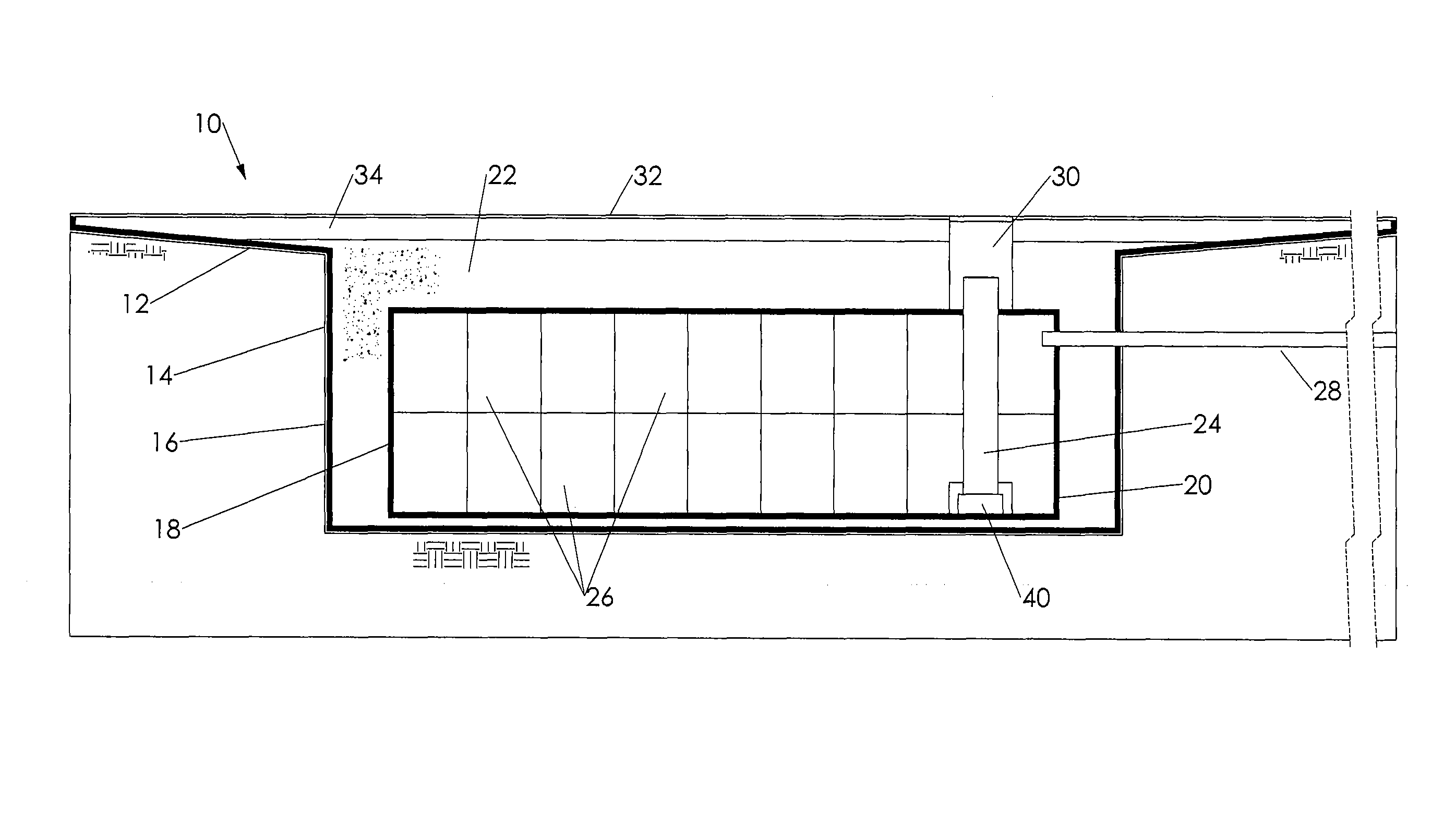
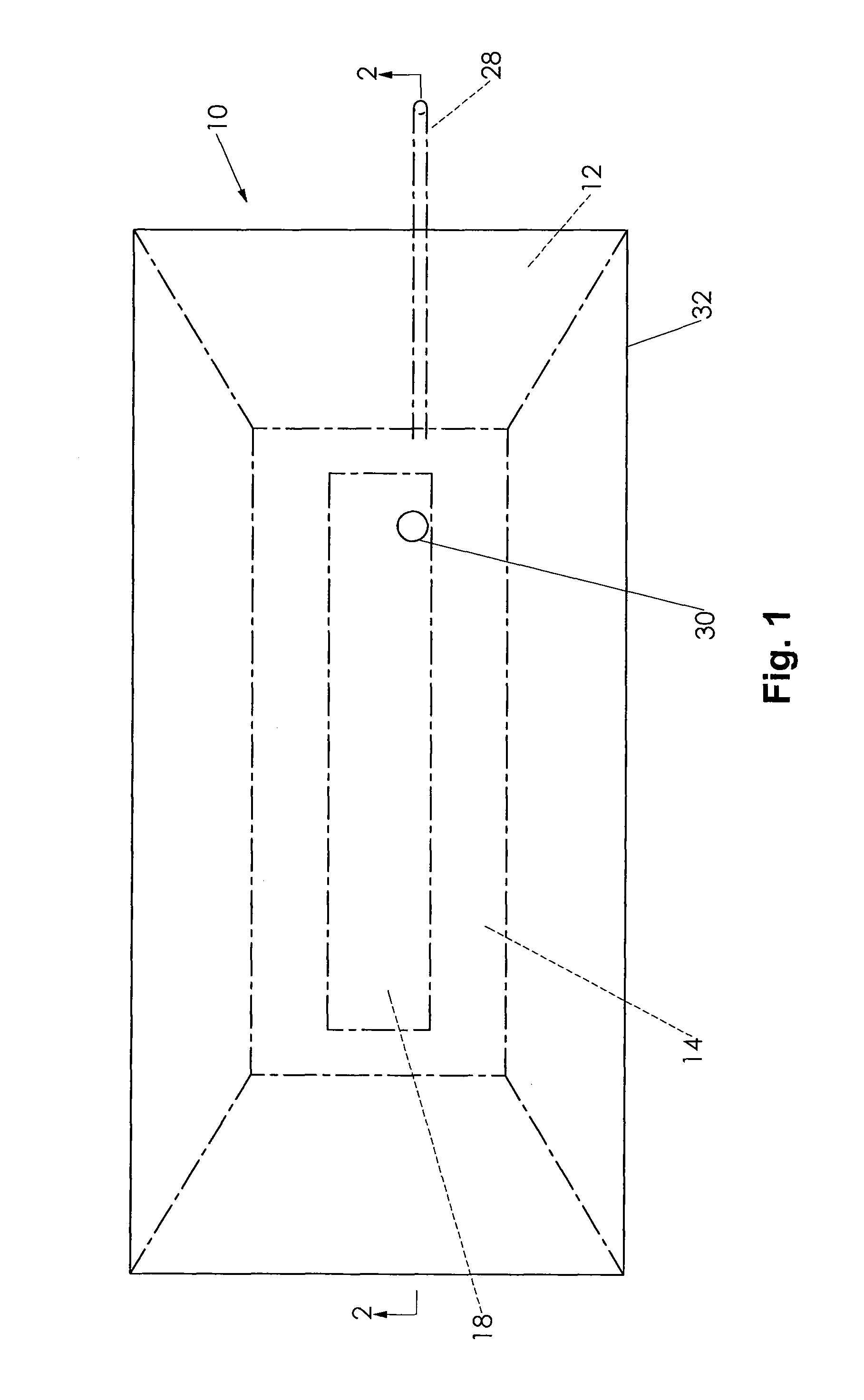
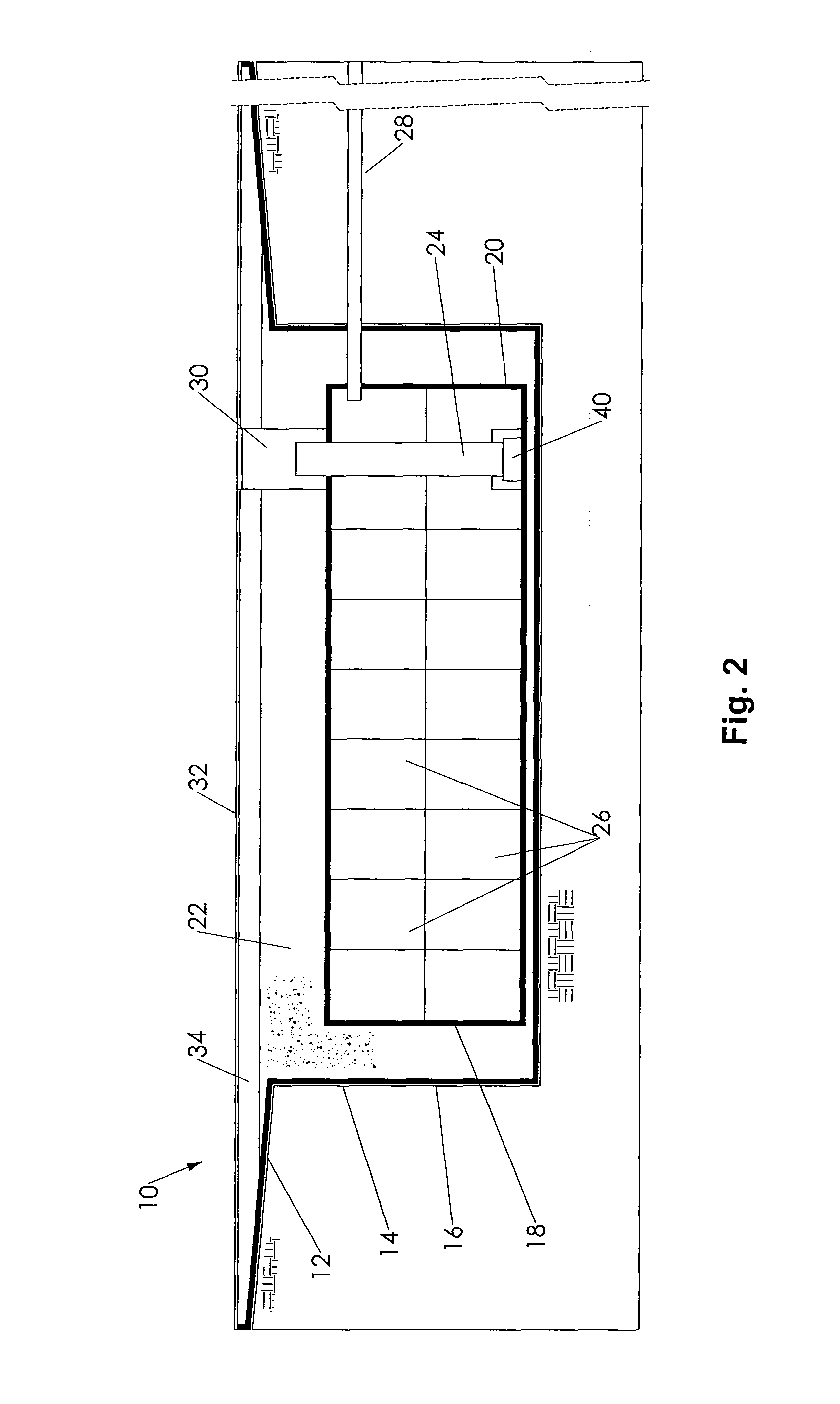
[0023]The water storage tank 18 is a load bearing structure that forms a void space for water storage. Although a prefabricated tank could be used, each of the preferred tank embodiments of the invention are constructed on site. The embodiments of the invention provide a more economical solution than prefabricated tanks. In a first embodiment, the water tank 18 comprises a prefabricated subunit structure 26 preferably at or near the bottom of the reservoir 14 as shown in FIG. 2. The subunit structure 26 can be constructed by assembling pre-molded plastic boxes on-site. Recycled plastic boxes made up of supporting cross beams have good load bearing capacity and create over 95% void space in which to store water. This is the preferred method of tank construction for the invention because of its ability to be constructed to any capacity with minimal excavation. It is also the embodiment that creates the largest percentage of void space by volume. There are multiple manufacturers of the...

second embodiment

[0030]FIG. 3 illustrates the invention in which the water storage tank 18 comprises one or more culvert sections 36. The culvert sections 36 preferably comprise pre-formed corrugated metal or concrete pipes placed at or near the bottom of the reservoir 14. Culvert sections 36 are preferably perforated to improve water flow into the hollow interior 38. Crushed stone 27, gravel and / or other permeable backfill material may be placed over and between sections 36. The remaining components of the water storage system are the same as described above.

third embodiment

[0031]FIG. 4 shows the invention in which the water storage tank 18 comprises a stone bed 42 having a significant void space for retention and storage of the collected water. Stone bed 42 may comprise plural layers of stone 27 or crushed rock. The bed preferable is covered with geotextile fabric to prevent the gravel and sand backfill, which has a smaller particle size, from migrating into the stone bed. Water travels through the remaining layers of the system as described above.


PUM


Abstract

A water drainage and harvesting system for use with an artificial turf field comprises permeable synthetic turf, permeable impact-absorbing sub-base material beneath the turf, a water collection basin below the field, a water reservoir below the collection basin, the basin and reservoir having an impermeable liner, a water tank in the reservoir, and a conduit from the tank that allows for filtered water to be pumped to the ground surface for reuse. The disclosure further relates to a method for the construction of such a water storage and conveyance system.

Description

CROSS-REFERENCE[0001]This application claims priority under 35 U.S.C. §119 from U.S. Provisional Patent Application Ser. No. 61 / 180,552, filed May 22, 2009.FIELD OF THE INVENTION[0002]The following invention relates to drainable artificial turf fields and other fields to drain water from the field surface and store such water for later use. More particularly, this invention relates to a subterranean system which drains water from a field surface, filters the water, and stores the filtered water beneath the field surface where it is accessible by way of a conduit.BACKGROUND[0003]Before the invention of artificial turf in the 1950s, natural grass was essentially the only way to create a playing field or landscape a park. Natural grass can be difficult to maintain, particularly in intemperate climates, and requires maintenance. In 1966, Astroturf was first installed in a professional sports complex in the Texas Astrodome and provided a year-round green playing field that did not need w...

Claims


Application Information

Patent Timeline
Patent Type & Authority Patents(United States)
IPC IPC(8): E02B13/00
CPCE02B11/00E03B3/03E01B13/02Y02A20/00Y02A20/108
Inventor HENRY, ERIC M.MCMAINS, TERRY J.SANCHEZ, TANYA R.
Owner SANCHEZ TANYA R
Why Eureka
Try Eureka