Eureka AIR delivers breakthrough ideas for toughest innovation challenges, trusted by R&D personnel around the world.

Control system and method, and communication device and method

a communication device and control system technology, applied in the field of control systems and methods, can solve the problems of increased power consumption, inability of in-vehicle wireless devices to correctly receive response signals, and inability to properly receive response signals, so as to achieve the effect of more efficient and accurate communication

Active Publication Date: 2012-07-17
OMRON AUTOMOTIVE ELECTRONICS CO LTD
View PDF15 Cites 5 Cited by
  • Summary
  • Abstract
  • Description
  • Claims
  • Application Information

AI Technical Summary

Benefits of technology

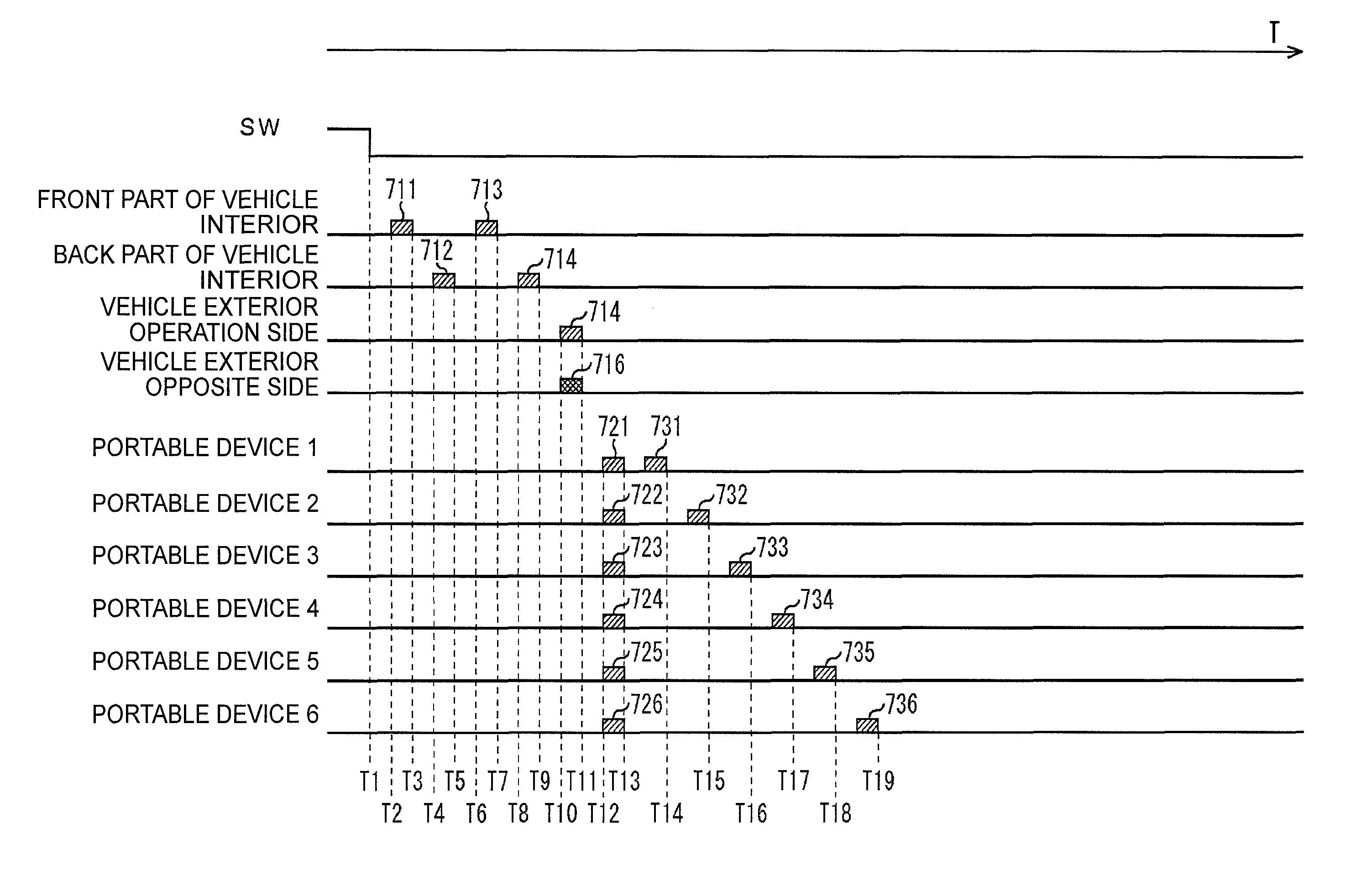
[0012]One or more embodiments of the present invention suppresses the occurrence of collision among the response signals and enables the communication to be carried out more efficiently and accurately by causing the portable device to transmit the response signal at different timing from each other with respect to the reception timing of the request signal.
[0059]According to one or more embodiments of the present invention, the information can be processed. In particular, the communication can be more efficiently and accurately carried out.

Problems solved by technology

However, if a plurality of portable devices exists within the communicable range of the in-vehicle wireless device, each of portable devices transmits the response signal with respect to the request signal at the same timing, whereby collision occurs among the response signals, and the in-vehicle wireless device may not be able to correctly receive such response signals.
However, in the case of the methods described in Japanese Unexamined Patent Publication Nos. 2008-150835 and 2008-150836, the in-vehicle wireless device has to transmit the request signal over a plurality of times (number of portable devices), and hence the load of the process of the in-vehicle wireless device may increase and the power consumption may increase as the number of portable devices increases.
Therefore, transmission and reception of the request signal and the response signal are required for the authentication of one portable device, and hence the processing time until the authentication becomes successful may undesirably increase.
The response time until the control operation from the instructing operation of the user increases if the processing time increases, and a so-called “state of late response” may occur, which gives an unpleasant feeling to the user.
Furthermore, in the case of the methods described in Japanese Unexamined Patent Publication Nos. 2008-150835 and 2008-150836, the possibility the communication will fail may increase since the number of communications increases.
In particular, the time (so-called response time) until the authentication becomes successful may increase if the transmission and reception of the request signal and the response signal for every portable device fail.

Method used


Image

  • Control system and method, and communication device and method
  • Control system and method, and communication device and method
  • Control system and method, and communication device and method

Examples


Embodiment Construction

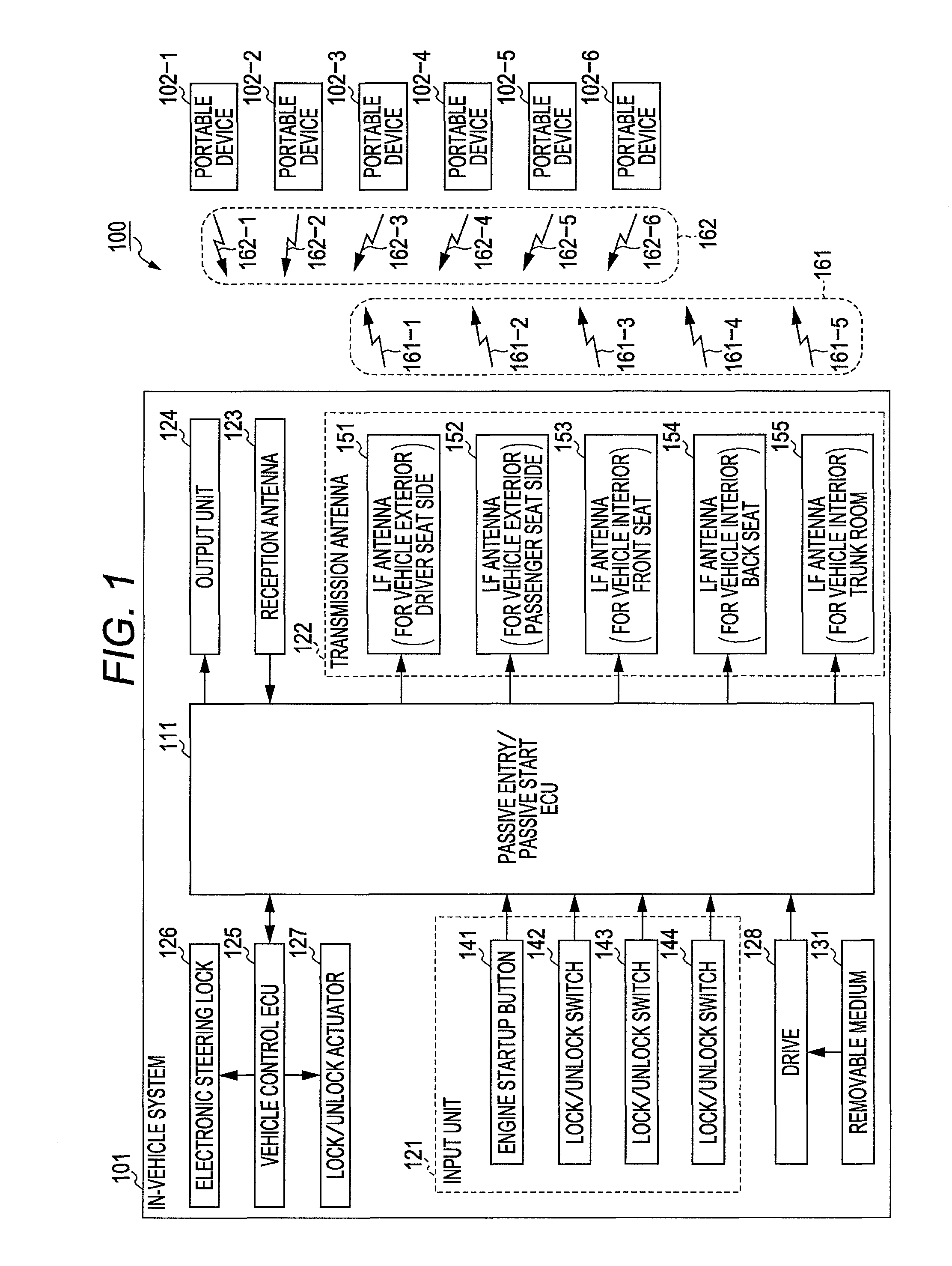
[0079]In embodiments of the invention, numerous specific details are set forth in order to provide a more thorough understanding of the invention. However, it will be apparent to one of ordinary skill in the art that the invention may be practiced without these specific details. In other instances, well-known features have not been described in detail to avoid obscuring the invention. FIG. 1 is a diagram showing a main configuration example of a control system applied with one or more embodiments of the present invention.

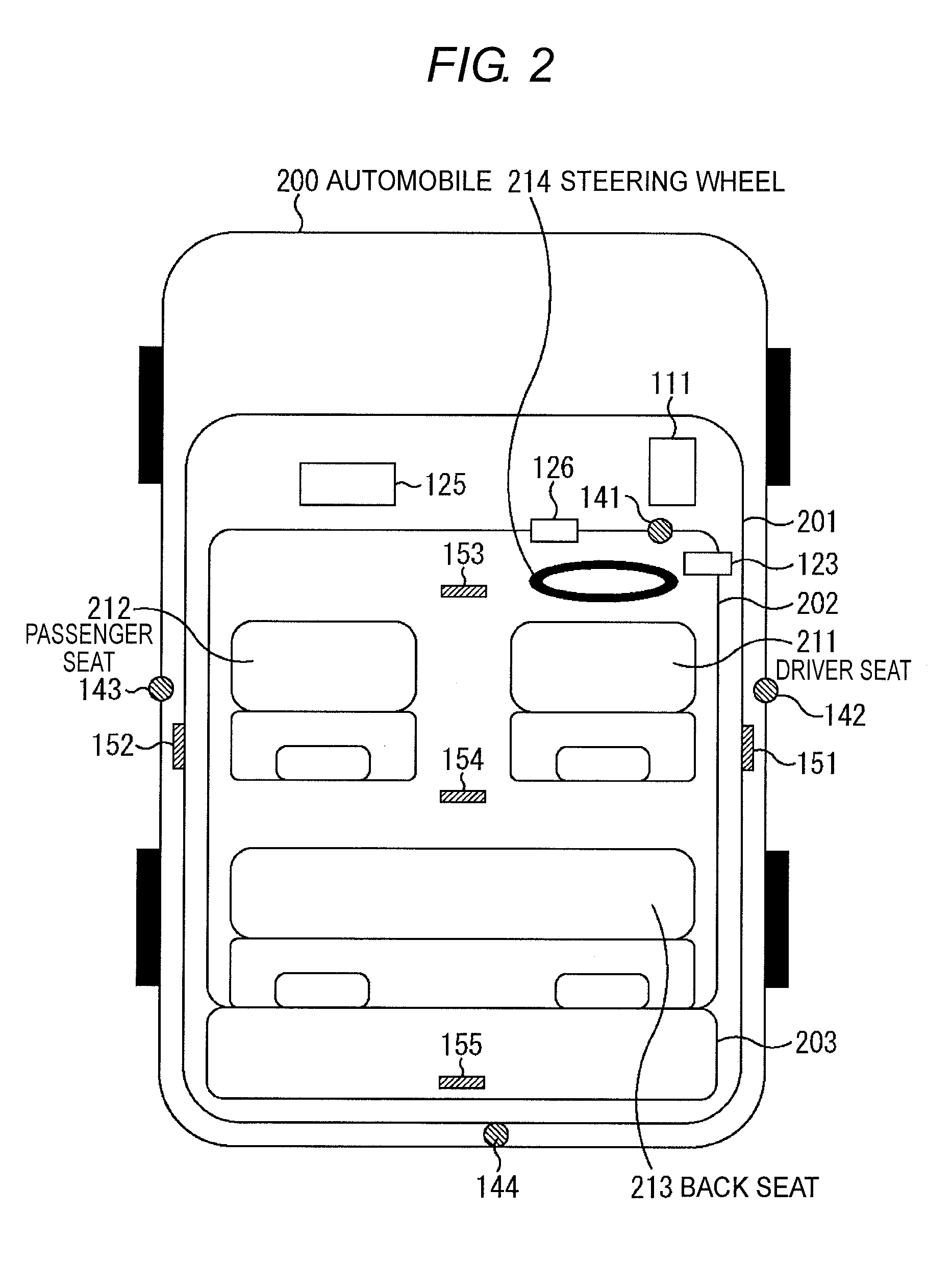
[0080]A control system 100 shown in FIG. 1 is a system for performing control of a predetermined operation (process) such as locking or unlocking (passive entry) of a door of an automobile, or startup (passive start) of the engine of the automobile based on a signal transmitted from a portable device having a wireless communication function.

[0081]The control system 100 can be used in the control of any operations and processes, but a system for performing the contro...


PUM


Abstract

A control system has a control device for performing a control of a predetermined process, and a communication device for communicating with the control device. The control device has a first transmission unit for transmitting a request signal requesting for transmission of a response signal to the communication device, a first reception unit for receiving the response signal transmitted through a predetermined procedure from the communication device in response to the request signal transmitted by the first transmission unit, an authentication unit for performing authentication of the communication device using identification information of the communication device contained in the response signal received by the first reception unit and identification information of the communication device registered in advance, and a process executing unit for executing the predetermined process when the authentication of the communication device by the authentication unit is successful. The communication device has a first storage unit for storing transmission scheduled time information indicating a time scheduled to transmit the response signal assigned to the communication device, a second reception unit for receiving the request signal transmitted from the first transmission unit, and a second transmission unit for transmitting the response signal corresponding to the request signal received by the second reception unit to the control device at a time different from times assigned to other communication devices based on the transmission scheduled time information stored in the first storage unit.

Description

BACKGROUND OF THE INVENTION[0001]1. Technical Field[0002]The present invention relates to control systems and methods, as well as, communication devices and methods, and in particular, to a control system and method, as well as, a communication device and method that suppress occurrence of collision and enable communication to be carried out more efficiently and accurately.[0003]2. Related Art[0004]A system that controls locking and unlocking of the door, for example, based on a signal transmitted from a portable device having a wireless communication function is conventionally known. For example, there is known a control system that receives a signal transmitted from a portable device having a wireless communication function by an in-vehicle wireless device mounted on an automobile, authenticates identification information of the portable device contained in the signal, and performs a predetermined process such as locking and unlocking of the door of the automobile or startup of th...

Claims


Application Information

Patent Timeline
Patent Type & Authority Patents(United States)
IPC IPC(8): G05B19/00G06F19/00B60R25/10H04Q5/22B60R25/01B60R25/24E05B49/00H04J3/16H04Q9/00
CPCH04L63/08
Inventor NISHIGUCHI, TADAOYASUDA, YUTAKAEBIZAWA, HIDEOTASHIRO, RYOHEIKASHIYAMA, MASATO
Owner OMRON AUTOMOTIVE ELECTRONICS CO LTD
Why Eureka
Eureka Blog
Learn More