Image processing method and image processing device

a technology of image processing which is applied in the field of image processing method and image processing device, can solve the problems of individual variability and the risk of misdiagnosis, and achieve the effect of facilitating the diagnosis of glaucoma more accurately and efficiently

Active Publication Date: 2012-08-14
KOWA CO LTD
View PDF2 Cites 0 Cited by
  • Summary
  • Abstract
  • Description
  • Claims
  • Application Information

AI Technical Summary

Benefits of technology

[0012]It is therefore an object of the present invention to provide an image processing method and an image processing device for automatically determining cup contour and disc contour and for minimizing individual variability (subjectivity) in computation of the C / D ratio so that assisted diagnosis of glaucoma may be carried out more accurately and efficiently.
[0016]The divided regions are then scanned radially from the established point while angles are shifted in order to detect in each region a point at which luminance variation or depth variation reaches a maximum, and the contour line of the disc region or cup region is determined from these points. This allows the disc contours or cup contours to be determined automatically, and assisted diagnosis of glaucoma to be carried out more accurately and efficiently.

Problems solved by technology

However, in the prior art, contour points of these were determined manually using an input device such as a mouse, and thus the determination involved some subjectivity, resulting in individual variability.
Individual variability is particularly great in the cup region, which significantly affects diagnosis of glaucoma and poses a risk of misdiagnosis.

Method used


Image

  • Image processing method and image processing device
  • Image processing method and image processing device
  • Image processing method and image processing device

Examples


Embodiment Construction

[0034]The present invention will now be described in detail with reference to the embodiment, which shows an ophthalmic measurement apparatus in which the ocular fundus under examination is stereographically photographed using a stereographical imaging optical system, and the photographed image undergoes three-dimensional measurement processing.

[0035]

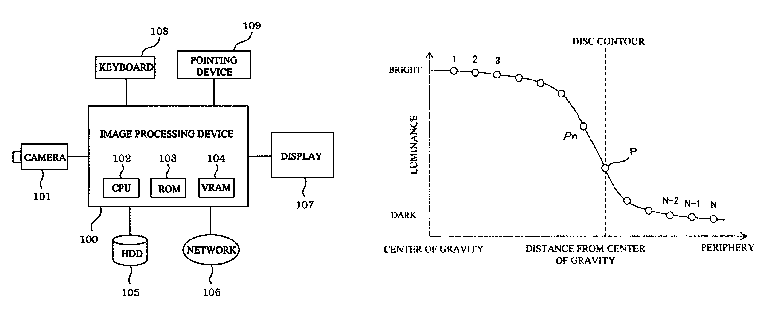
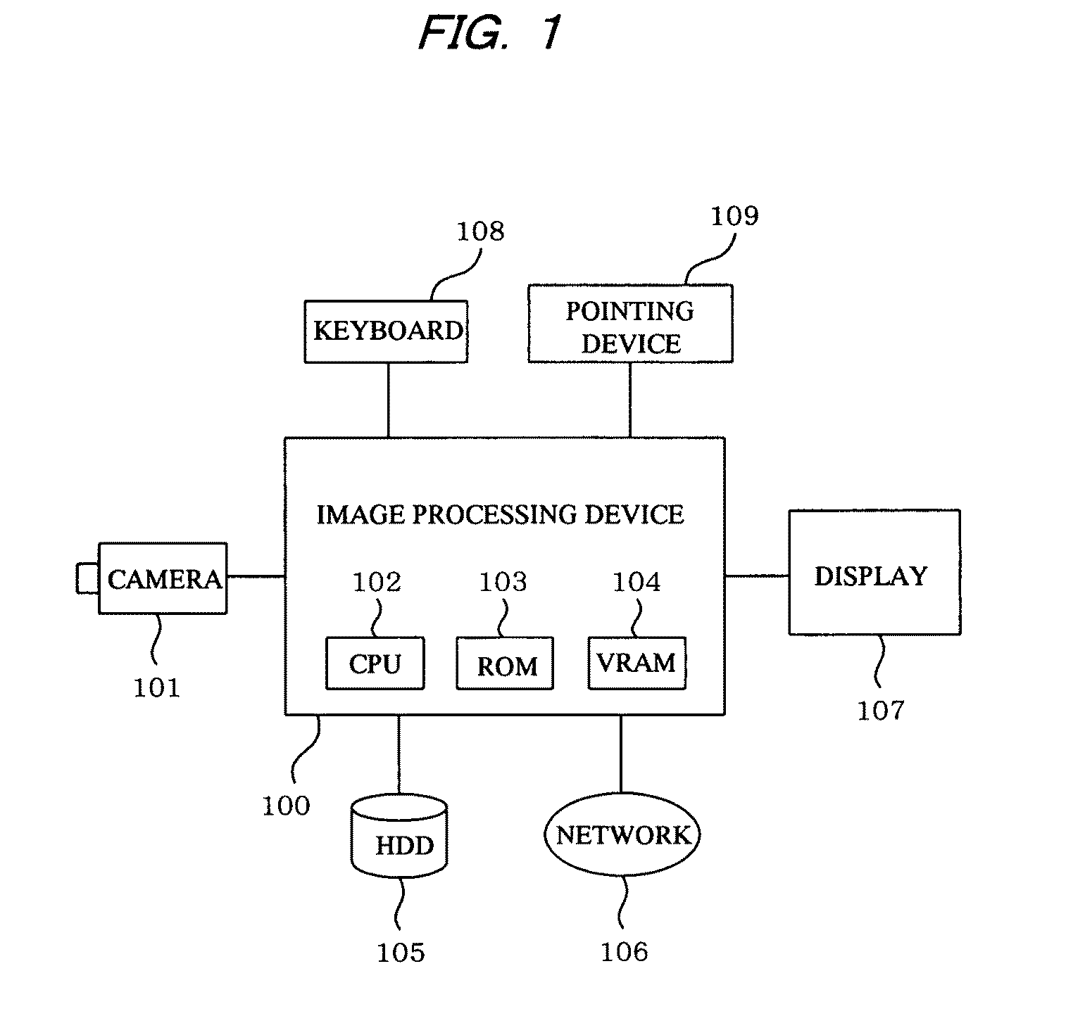
[0036]FIG. 1 shows a configuration of an ophthalmic measurement apparatus showing one embodiment of the present invention. In FIG. 1, symbol 101 denotes a fundus camera. In order to photograph the ocular fundus under examination (not shown) under prescribed photographic conditions, the fundus camera is equipped with mechanisms such as, for example, an alignment mechanism, a monocular photography mechanism, and a stereographic photography mechanism. The fundus camera 101 has an image pickup device for color photography, such as a three-plate CCD or CMOS sensor for example, and outputs ocular fundus color image data of the eye under exami...


PUM


Abstract

An ocular fundus image is captured by a fundus camera. Blood vessel regions are erased from the ocular fundus image, and a luminance region greater than a prescribed luminance threshold value and having an area equivalent to a predetermined standard disc area is extracted as a region having a standard disc area. The region having the standard disc area is divided into a plurality of regions by a plurality of dividing lines extending radially from the center of gravity thereof, and divided regions are scanned radially from the center of gravity while angles are shifted to detect in each individual region a point at which luminance variation reaches a maximum. The contour line of the disc region is derived from these points.

Description

BACKGROUND OF THE INVENTION[0001]1. Field of the Invention[0002]The present invention relates to an image processing method and an image processing device for processing images of the optic disc region of a photographed ocular fundus under examination.[0003]2. Description of the Related Art[0004]In the field of methods for diagnosing the ophthalmic disorder of glaucoma, image processing is known which evaluates the shape and size of the optic disc (hereinafter referred to simply as the disc or disc region) in an image of the ocular fundus.[0005]When the magnitude of optic disc cupping is to be evaluated via image analysis, they define the diameter ratio C / D of the diameter of the optic disc cupping, called the “cup”, and the diameter of the optic disc, called the “disc” (see Japanese Patent No. 3594468).[0006]The medial region lying between the disc region and the cup region is termed the “rim” and observation of the width of this rim is one method for the examiner to diagnose glauc...

Claims


Application Information

Patent Timeline
Patent Type & Authority Patents(United States)
IPC IPC(8): A61B3/14A61B3/00
CPCG06T7/0083G06T2207/10012G06T2207/30041G06T2207/20168G06T2207/20148G06T7/12G06T7/136
Inventor NAKAGAWA, TOSHIAKITAKIMOTO, SHIGERU
Owner KOWA CO LTD
Why Eureka
Try Eureka